Electronic expansion valve
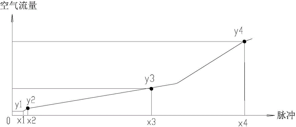
An electronic expansion valve, valve port technology, applied in the direction of lift valve, valve details, valve device, etc., can solve the problems of inability to make full use of the pulse in the small opening area, and it is difficult to accurately control the 0-pulse flow, so as to improve the consistency, The effect of expanding the adjustment range and reducing the manufacturing cost
- Summary
- Abstract
- Description
- Claims
- Application Information
AI Technical Summary
Problems solved by technology
Method used
Image

Examples
no. 1 approach
[0046] Please refer to Figure 5 , Figure 6 . in, Figure 5 It is a structural schematic diagram of the electronic expansion valve according to the first embodiment of the present invention, Figure 6 is a schematic diagram of the needle structure of the electronic expansion valve in the first embodiment.
[0047] Such as Figure 5 As shown, the electronic expansion valve includes a valve body 1 and a coil (not shown in the figure), the valve body 1 includes a valve seat 11, a first connecting pipe 12 and a second connecting pipe 13 connected to the valve seat 11 for refrigerant circulation, The top of valve seat 11 is also fixedly connected with shell 14, and in the inside of shell 14, is provided with the magnetic rotor 15 that responds to the signal of coil and rotates, and the screw mandrel 16 that is fixedly connected with magnetic rotor 15, and cooperates with screw mandrel, wire The rotational movement of the rod is converted into the lifting movement of the nut 1...
no. 2 approach
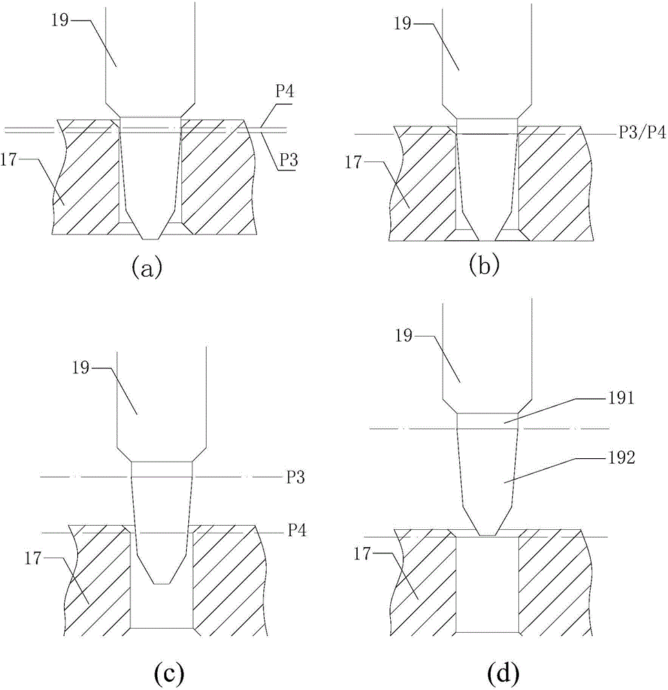
[0059] Please refer to Figure 10 , Figure 10 It is a schematic diagram of the cooperation structure between the valve needle and the valve port of the electronic expansion valve according to the second embodiment of the present invention.
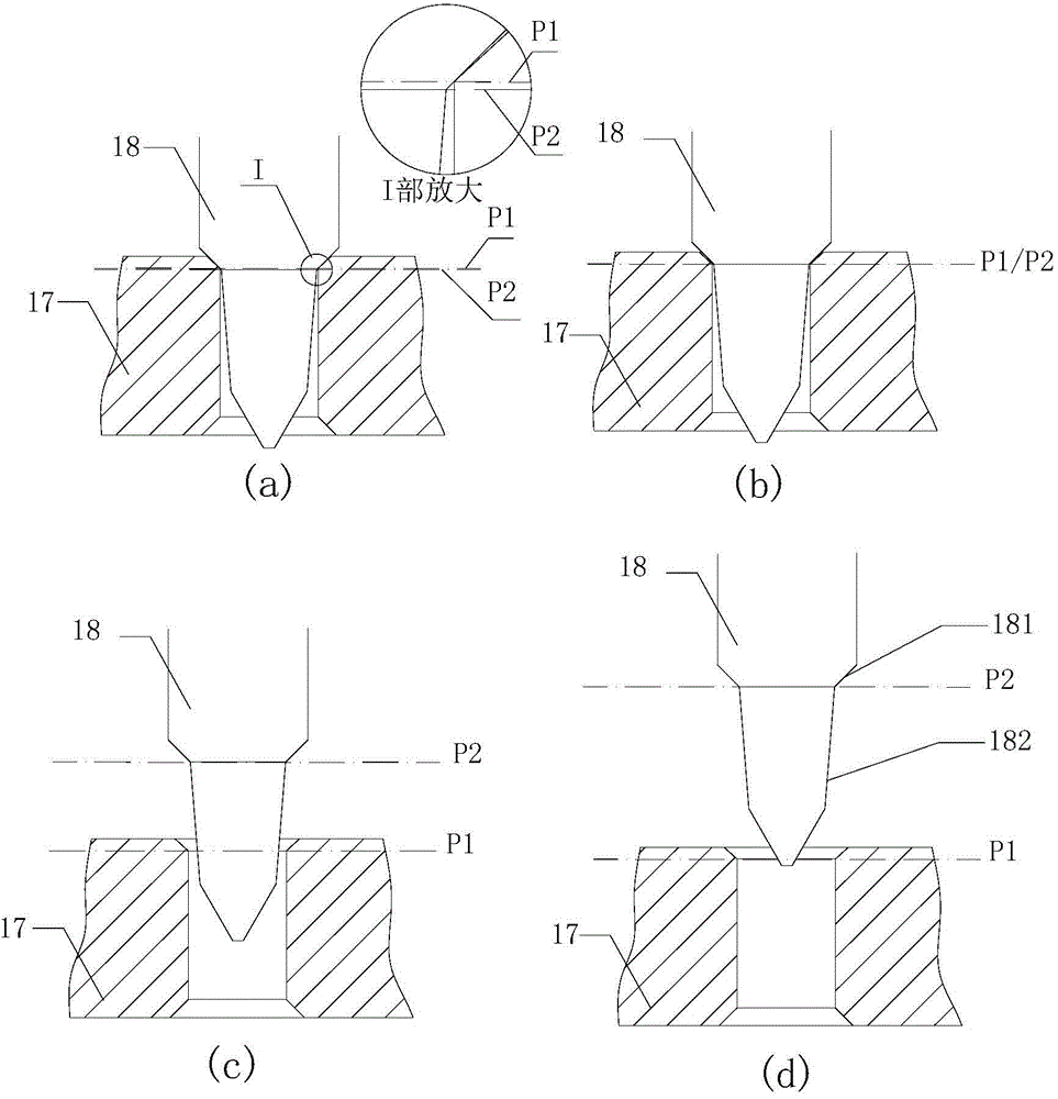
[0060] In this embodiment, the structure of the valve port 22 is the same as that of the first embodiment, including a first valve port conical surface 221, a straight portion 222, and a second valve port conical surface 223 arranged in sequence, wherein the straight portion 222 is generally in the shape of Cylindrical, the first taper surface 221 of the valve port and the second taper surface 223 of the valve port both extend along the axial direction away from the straight portion 222 , and gradually increase the inner diameter, thereby forming an inner taper shape. The junction of the first taper surface 221 of the valve port and the straight portion 222 forms a junction line, and the plane where it is located is the second plane N2. ...
no. 3 approach
[0064] Please refer to Figure 11 , Figure 11 It is a schematic diagram of the coordination structure between the valve needle and the valve port of the electronic expansion valve according to the third embodiment of the present invention.
[0065] In this embodiment, the valve needle 21 is the same as the first embodiment, including a main body section 211 connected with the screw rod, a first valve needle cone surface 212 connected with the main body section 211 and a valve needle cone surface 212 connected with the first valve needle cone surface 212 . The second valve needle cone surface 213 and the third valve needle cone surface 214 can be set according to the requirement of flow regulation.
[0066] The valve port 32 is generally a hollow cylindrical straight section 321 without any conical surface. The maximum diameter of the second needle conical surface 213 is larger than the inner diameter of the straight section 321 . The top of the valve port defines a second p...
PUM
 Abstract
Description
Claims
Application Information
 - Generate Ideas
- Intellectual Property
- Life Sciences
- Materials
- Tech Scout
- Unparalleled Data Quality
- Higher Quality Content
- 60% Fewer Hallucinations
Browse by: Latest US Patents, China's latest patents, Technical Efficacy Thesaurus, Application Domain, Technology Topic, Popular Technical Reports.
© 2025 PatSnap. All rights reserved.Legal|Privacy policy|Modern Slavery Act Transparency Statement|Sitemap|About US| Contact US: help@patsnap.com