Heating structure for pipeline and pipeline using same

A heating structure and pipeline technology, applied in pipeline heating/cooling, pipeline protection, pipeline protection through heat insulation, etc., can solve the problems of reducing the service life of heating cables, unbalanced pipeline temperature, and increasing use costs, etc., to reduce insulation aging The effect of fast speed, extended service life, and no starting current

Inactive Publication Date: 2015-09-23
WUXI AIKESEN THERMAL CONTROL TECH
View PDF8 Cites 1 Cited by
  • Summary
  • Abstract
  • Description
  • Claims
  • Application Information

AI Technical Summary

Problems solved by technology

This method of binding electric heating cables on the outer wall of the pipeline to achieve heating and antifreezing is not only cumbersome to operate, but also has poor heat conduction effect. Since the electric heating cables use point conduction to generate heat, the energy consumption is large, and in the process of heat conduction, it is easy to appear The temperature of the pipeline is unbalanced, so the heating power must be increased to achieve the desired effect, but increasing the power will also cause aging and damage to the heating cable, reducing the service life of the heating cable and increasing the cost of use

Method used


Image

  • Heating structure for pipeline and pipeline using same
  • Heating structure for pipeline and pipeline using same

Examples


Embodiment Construction

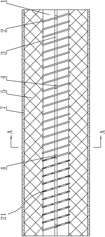
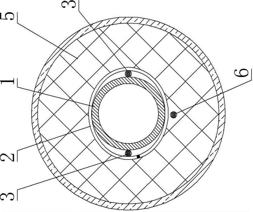
[0017] Such as Figure 1 to Figure 2 As shown, the pipeline heating structure includes a heating layer coated on the outer wall of the pipeline 1. Two parallel electric busbars 3 are arranged between the heating layer and the outer wall of the pipeline 1. The heating layer includes an electric heating wire 2, and the electric heating wire 2 Evenly wound on the outer wall of the pipeline 1 along the length direction of the pipeline 1, the energized busbar 3 is bound by the electric heating wire 2 and attached to the outer wall of the pipeline 1, the outer periphery of the energized busbar 3 is covered with a busbar insulation layer, and the busbar insulation layer is along the energized busbar 3 Cutouts 4 are arranged at intervals in the length direction of the busbar, and the energized busbar 3 is exposed at the cutout 4, and the energized busbar 3 at the cutout 4 is in contact with the electric heating wire 2; The winding lengths between adjacent slits 4 are equal, and the el...


PUM


Abstract

The invention provides a heating structure for a pipeline and a pipeline using the same. The heating structure can heat the surface of the pipeline evenly and is good in heat conduction effect, low in energy consumption and long in service life. The invention further provides a water pipe for a solar water heater using the heating structure, a smoke sampling pipe using the heating structure, and an oil pipe for a diesel engine using the heating structure. The heating structure comprises a heating layer covering the outer wall of the pipeline, wherein two parallel electrified buses are arranged between the heating layer and the outer wall of the pipeline, the heating layer comprises an electric heating wire which is evenly wound around the outer wall of the pipeline in the length direction of the pipeline, the electrified buses are bound and attached to the outer wall of the pipeline through the electric heating wire, the periphery of each electrified bus is coated with a bus insulating layer, notches are formed in each bus insulating layer at intervals in the length direction of the electrified bus, the electrified buses are exposed from the notches, and the portions, provided with the notches, of each electrified bus make contact with the electric heating wire.

Description

technical field [0001] The invention relates to a pipeline heating structure and a pipeline using the heating structure. Background technique [0002] Existing pipelines generally realize the heat preservation operation of the fluid through the set of thermal insulation sleeves. For some fluids with special requirements for conveying temperature, electric heating cables are generally attached to the outer wall of the pipeline. The electric heating cables are installed along the length of the pipeline, and then Set the insulation pipe sleeve, and then wrap the waterproof layer outside the insulation pipe sleeve, for example: (1) The water pipe of the solar water heater, including the water outlet pipe and the water inlet pipe, in order to solve the problem of freezing blockage caused by low temperature in winter, the water supply pipe is insulated Before the pipe cover, the construction party generally lays the heating cable on the water pipe along the length direction of the...

Claims


Application Information

Patent Timeline
Patent Type & Authority Applications(China)
IPC IPC(8): F16L53/00F16L59/14
CPCF16L53/34F16L59/14
Inventor 陈晓龙陈磊
Owner WUXI AIKESEN THERMAL CONTROL TECH
Why Eureka
Try Eureka