Carbon dioxide exploder

A carbon dioxide and detonator technology, applied in blasting and other directions, can solve problems affecting production efficiency, poor sealing, troubles, etc., and achieve the effects of prolonging service life, convenient handling, and improving safety factor

Active Publication Date: 2015-09-23
湖南烈岩科技有限公司
View PDF7 Cites 10 Cited by
  • Summary
  • Abstract
  • Description
  • Claims
  • Application Information

AI Technical Summary

Problems solved by technology

Existing carbon dioxide extractors, such as the carbon dioxide extractor in the Chinese invention patent with application number 201310001976.6, use a heater and a heating agent to heat, and the heating agent is installed in a paper tube, and the heating agent undergoes a chemical reaction by electrifying with an electric ignition head After heating up, the heat is transferred to the liquid carbon dioxide in the main tube through the wall of the paper tube. The heating agent is discarded after one-time use. It is very troublesome to remove the filling head and reinstall the hot heating agent; The energy channel and the filling chamber of the main pipe are sealed with a constant-pressure energy-discharging piece. When the liquid carbon dioxide in the main pipe gasifies and expands to a certain pressure, the constant-pressure energy-discharging piece is broken and rushed out of the energy-discharging channel. The energy sheet is also scrapped after one-time use. It is necessary to remove the energy release head and reinstall it on the main pipe, which is very time-consuming and affects production efficiency. Repeated disassembly will cause problems such as poor sealing

Method used


Image

  • Carbon dioxide exploder

Examples


Embodiment 1

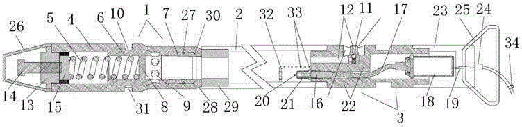
[0021] This embodiment includes an energy relief valve 1, a main body pipe 2 and a starting mechanism 3, the energy relief valve 1 and the starting mechanism 3 are respectively fixed at both ends of the main body pipe 2, and the energy relief valve includes an energy relief valve sleeve 4 , energy release spool, spring 5, described energy release spool is the ladder cylindrical shape of two ends open, comprises the compression cylinder 6 of large external diameter, the energy discharge cylinder 7 of small external diameter, between compression cylinder, energy discharge cylinder There is a partition 8 in between, and the inner cavity of the energy relief valve sleeve 4 is a stepped inner cavity, including a compression chamber with a large inner diameter and an energy release chamber with a small inner diameter. One end of the energy relief valve sleeve 4 is sealed with the main pipe 2 The other end is a closed end, the spring 5 is set in the energy release valve sleeve 4, and ...


PUM


Abstract

The invention discloses a carbon dioxide exploder, and belongs to the technical field of exploding devices. The carbon dioxide exploder comprises an energy relief valve, a main body pipe and a start mechanism. The energy relief valve and the start mechanism are fixed to the two ends of the main body pipe respectively. The energy relief valve comprises an energy relief valve sleeve, an energy relief valve element and a spring. The energy relief valve element is in a ladder cylinder shape with the two ends being open. The exploder comprises a compression cylinder with the large outer diameter and an energy relief cylinder with the small outer diameter. A partition plate is arranged between the compression cylinder and the energy relief cylinder. Correspondingly an inner cavity of the energy relief valve sleeve is a ladder-shaped inner cavity. One end of the energy relief valve sleeve is connected with the main body pipe in a sealed mode. The spring is arranged in the energy relief valve sleeve. One end of the spring enters the compression cylinder. Energy relief inner holes are formed in the energy relief cylinder in the peripheral direction. Energy relief outer holes are formed in the middle of the energy relief valve sleeve in the peripheral direction. By the adoption of the high-tension ignition exploder and the energy relief valve capable of achieving automatic reset, relighting and repeat energy relief can be achieved conveniently and fast.

Description

technical field [0001] The invention relates to the technical field of blasting devices, in particular to an extractor using carbon dioxide as an explosive material. Background technique [0002] Explosive blasting has experienced a history of thousands of years, and it has been used so far because there is no alternative good method. It is still one of the coal mining methods at present. Explosive blasting is powerful and fierce, and it is a typical open flame blasting. However, there are many defects in open flame blasting, and there are high requirements for use conditions, use environment, and daily management. Simultaneously, the cases of other accidental explosions due to explosives also occur from time to time, which also caused economic losses. [0003] Carbon dioxide gas blasting is a physical blasting that uses liquid carbon dioxide to quickly gasify and expand when heated, so as to do work externally. It will not produce toxic and harmful gases such as carbon mo...

Claims


Application Information

Patent Timeline
Patent Type & Authority Applications(China)
IPC IPC(8): F42D1/045
Inventor 周明
Owner 湖南烈岩科技有限公司
Why Eureka
Try Eureka