Fixed line feed apparatus of ultrasonic probe in ultrasonic wave stress measurement system

A technology of stress measurement and ultrasonic probe, which is applied in the direction of measuring devices, measuring forces, instruments, etc., can solve the problem of inability to accurately control the coupling state of the probe and the component to be measured, the inability to ensure that the probe is consistent with the component to be measured, and affect the accuracy of ultrasonic testing methods, etc. problem, achieve the effect of reducing influence, low device cost and improving measurement accuracy

Active Publication Date: 2015-09-23
成都交大智辉激光科技有限公司
View PDF6 Cites 6 Cited by
  • Summary
  • Abstract
  • Description
  • Claims
  • Application Information

AI Technical Summary

Problems solved by technology

At present, most of the ultrasonic probes are directly fixed on the surface of the component under test by hand or simply fixed for ultrasonic testing; The coupling state between them is the same as that used for calibration; resulting in large measurement errors and affecting the accuracy of ultrasonic testing

Method used


Image

  • Fixed line feed apparatus of ultrasonic probe in ultrasonic wave stress measurement system
  • Fixed line feed apparatus of ultrasonic probe in ultrasonic wave stress measurement system
  • Fixed line feed apparatus of ultrasonic probe in ultrasonic wave stress measurement system

Examples


specific Embodiment approach

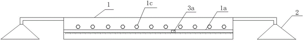
[0044] Figure 1-5 As shown, a specific embodiment of the present invention is: a fixed running device of an ultrasonic probe in an ultrasonic stress measurement system, comprising:

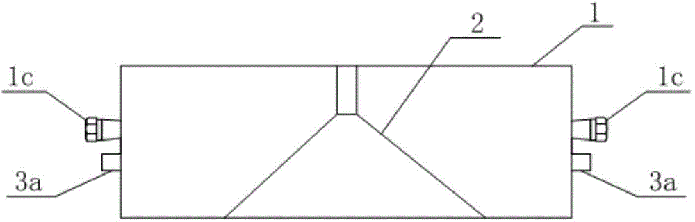
[0045] The track frame 1 with a "door"-shaped cross section is provided with horizontal through grooves 1a on opposite sides of the track frame 1 along the length direction, and the two horizontal through grooves 1a are located on the same horizontal plane; the upper part of the through groove 1a is along the horizontal The direction is provided with a row of tapered bolt holes 1b, and the maximum diameter of the tapered bolt 1c that cooperates with the tapered bolt holes 1b is greater than the maximum diameter of the tapered bolt holes 1b; the material that constitutes the tapered bolt holes 1b, the tapered bolt holes Between 1b and the through groove 1a and under the through groove 1a are elastic materials;

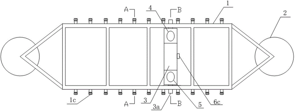
[0046] Fixed suction cups 2 fixed to both ends of the track frame 1 along the length ...

Embodiment 2

[0058] Figure 6 , Figure 7 As shown, another specific implementation of the present invention is: this embodiment is basically the same as Embodiment 1, the only difference is that the probe fixing cavity 4 described in this example is embedded and fixed in the probe fixing wedge 3 The upper left area; the probe fixing cavity 2 5 is embedded and fixed in the upper right area of ​​the probe fixing wedge 3 .

[0059] Use effect of the present invention can be verified and explained by following test:

[0060] Select the aluminum alloy material A7N01S-T5, 700*230 butt joint test plate commonly used in high-speed trains, and arrange the residual stress test points according to the same distance, as Figure 6 mentioned.

[0061] Install the fixed running device in the above method, connect the ultrasonic generator to the ultrasonic testing system, and conduct residual stress test on points 1-7. The test results are shown in the table below.

[0062] test point

[00...


PUM


Abstract

The invention discloses a fixed line feed apparatus of an ultrasonic probe in an ultrasonic wave stress measurement system. The apparatus comprises a track rack, fixing sucking discs, a probe fixing wedge, a probe fixing chamber 1, a probe fixing chamber 2 and a coupling monitor, wherein a cross section of the track rack is in a ''door'' shape; two side surfaces of the track rack along a length direction are provided with horizontal straight slots; a tapered bolt hole and a tapered bolt are arranged above the straight slots; a material which is used to form the tapered bolt hole, a material between the tapered bolt hole and the straight slots and a material below the straight slots are an elastic material; the fixing sucking discs are arranged on two ends of the track rack; the probe fixing wedge is arranged in the track rack; left and right side surfaces of the probe fixing wedge are provided with slide handles; the probe fixing chamber 1 and the probe fixing chamber 2 are fixed to an upper-left portion and an upper-right portion of the probe fixing wedge; the coupling monitor is formed by a monitoring indication lamp, a pressure sensor which is electrically connected to the monitoring indication lamp and a resistor sensor. By using the apparatus, the ultrasonic probe can be accurately positioned; a coupling state between the ultrasonic probe and a component to be measured is guaranteed to be consistent with a coupling state used during calibration; measurement precision of an ultrasonic wave detection method is increased.

Description

technical field [0001] The invention relates to a fixed running device of an ultrasonic probe in an ultrasonic stress measurement system, belonging to the field of residual stress testing. Background technique [0002] my country's industry is in a period of rapid development. Large-scale structures, oil pipelines, high-speed trains, aerospace, nuclear power equipment, etc. have to use a lot of welding. Residual stress is the main cause of welded joint damage. Accurate detection of residual stress is the key to solving residual stress premise of the problem. The detection methods of residual stress are mainly divided into two methods: destructive testing and non-destructive testing. Although the method of detecting residual stress by the destructive method has high accuracy, it will cause irreversible damage to the equipment itself. Therefore, in recent years, non-destructive testing of residual stress has received more and more attention. [0003] The methods for non-dest...

Claims


Application Information

Patent Timeline
Patent Type & Authority Applications(China)
IPC IPC(8): G01L1/25
Inventor 苟国庆朱其猛陈辉朱忠尹马传平陈佳刘艳覃超安江丽付正鸿
Owner 成都交大智辉激光科技有限公司
Why Eureka
Try Eureka