
A test device that can automatically adjust the lip opening angle of the supercombustion inlet

A technology of automatic adjustment and test device, applied in aerodynamic test, measurement device, test of machine/structural parts, etc., can solve the problems of real-time measurement of lip angle, energy waste, inaccurate test results, etc., to improve control and acquisition accuracy, reducing interference effects, and improving the effect of response characteristics

Active Publication Date: 2018-06-01
CHINA ACAD OF AEROSPACE AERODYNAMICS
View PDF7 Cites 0 Cited by
  • Summary
  • Abstract
  • Description
  • Claims
  • Application Information

AI Technical Summary

Problems solved by technology

[0004] In the field of intake port test, since the intake port model has been scaled down, the size has been reduced a lot, and it is often designed into different solid blocks to change the lip of the intake port. This method can only change a limited number of lips step by step. For mouth corners, each air blow can only obtain the aerodynamic performance of the air inlet at one lip angle, resulting in a huge waste of energy; at the same time, it cannot obtain the dynamic characteristics of the air inlet when the lip angle is continuously changed, and it is also impossible to obtain continuously variable lip angles. Self-starting performance of inlet port
[0005] In recent years, some designers have also tried to install a worm-worm combined motor on the intake port to drive the lip to rotate through the forward and backward movement of the worm, but this direct drive method has some disadvantages, such as the drive mechanism must be installed near the lip, which is harmful to the The flow field at the inlet of the inlet has a great influence, making the test results inaccurate
On the other hand, this method cannot install an angle sensor, that is, it cannot measure the lip angle in real time during the test, so the test system can only be controlled in an open-loop manner, and closed-loop control cannot be realized, and its anti-interference ability is poor

Method used


Image

  • A test device that can automatically adjust the lip opening angle of the supercombustion inlet

Examples


Embodiment Construction

[0032] In order to make the above objects, features and advantages of the present invention more comprehensible, specific implementations of the present invention will be described in detail below in conjunction with the accompanying drawings.

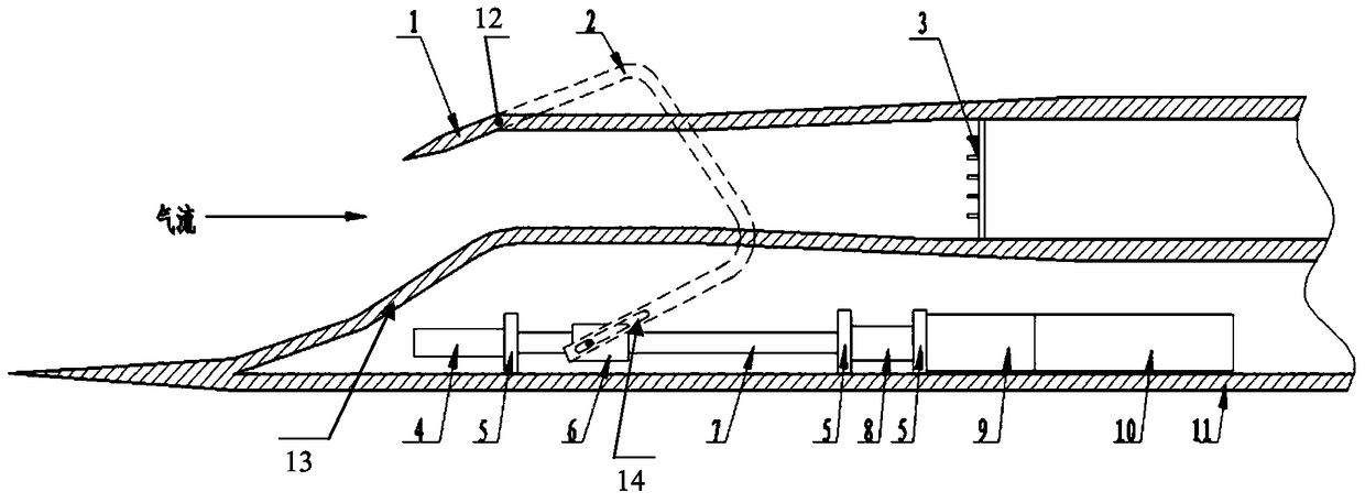
[0033] see figure 1 , the present invention provides a test device that can automatically adjust the opening angle of the lip of the supercombustion inlet, including: a fixed part 13 and a movable part 1 that define the lip of the inlet, and the movable part The end is pivotally connected to the wall of the air inlet through a pivot 12; the lead screw 7; the movable nut 6, which is threadedly matched with the lead screw, is sleeved on the lead screw in a manner that can move along the lead screw; Rod 2, one end of which is connected to the movable part, and the other end is connected to the movable nut; a rotary drive mechanism, which is connected to one end of the lead screw, drives the lead screw to rotate so that the movable part D...


PUM


Abstract

The invention discloses a test device capable of automatically adjusting the opening angle of the lip of a supercombustion inlet, comprising: a fixed part and a movable part defining the lip of the inlet, and the end of the movable part is articulated by a pivot to the inlet wall; lead screw; movable nut; connecting rod connected at one end to the movable part and at the other end to the movable nut; rotary drive mechanism which rotates the lead screw to rotate the movable part relative to the pivot , so as to change the angle of the inlet lip; the angle sensor; the control module, which pre-establishes the corresponding relationship between the rotation angle of the screw and the angle of the inlet lip, according to the corresponding relationship and the real-time detection of the screw Control the rotation drive mechanism to output a certain rotation drive force, so that the real-time intake lip angle reaches the specified value or changes according to the specified law, and realizes closed-loop control. The invention can obtain the dynamic aerodynamic performance and the self-starting performance of the intake passage when the lip of the intake passage changes continuously.

Description

technical field [0001] The invention relates to the field of air inlet wind tunnel tests, in particular to a test device capable of automatically adjusting the lip opening angle of a supercombustion inlet. Background technique [0002] The intake port is an important aerodynamic part of the ramjet engine, and its design form and parameters have a significant impact on the engine's operating capability and performance. Hypersonic inlets usually adopt a fixed geometry scheme, and the lip angle generally does not change during flight. However, the actual flight envelope of the inlet generally contains both the lower Mach number and the higher Mach number. The inherent characteristic of the inlet itself is that it must be self-starting at a small lip angle (that is, a small capture area) at low supersonic speeds, and a large lip angle (that is, a large capture area) is required at high supersonic speeds. Get ideal flow and compression performance. [0003] As mentioned above,...

Claims


Application Information

Patent Timeline
Patent Type & Authority Patents(China)
IPC IPC(8): G01M9/00
Inventor 吴军飞王复春童木华陈强欧平
Owner CHINA ACAD OF AEROSPACE AERODYNAMICS
Learn More