Display panel and display device

A technology of display panel and display area, applied in static indicators, instruments, etc., can solve the problem of difficult pixel charging, and achieve the effect of good display effect and narrow frame

Active Publication Date: 2015-09-23
BOE TECH GRP CO LTD
View PDF10 Cites 32 Cited by
  • Summary
  • Abstract
  • Description
  • Claims
  • Application Information

AI Technical Summary

Problems solved by technology

However, with the increase of the resolution and size of the display panel, the load of each GOA also increases, that is to say, the size of the thin film transistor (TFT) of each shift register in the GOA circuit is also larger, thus resulting in The harder it is to charge a pixel, the wider the bezel of the corresponding display panel

Method used


Image

  • Display panel and display device
  • Display panel and display device
  • Display panel and display device

Examples


Embodiment 1

[0033] This embodiment provides a display panel, including a display area and a peripheral area, the display area includes a plurality of gate lines and a plurality of data lines intersecting, and the gate lines and the data lines intersect to define a plurality of pixel units , wherein at least one of the grid lines includes at least two grid line segments disconnected, each of the grid line segments controls at least one pixel unit, and the display area is divided into at least two according to the disconnection position of the grid line segments. sub-display areas, at least one of the sub-display areas is provided with a shift register unit connected to the gate line segment, and the shift register unit is used to provide a gate scan signal for the gate line segment connected to it.

[0034] In the display panel of this embodiment, at least one of the sub-display regions is provided with a shift register unit connected to the gate line segment, that is to say at least part o...

Embodiment 2

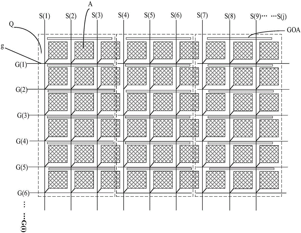
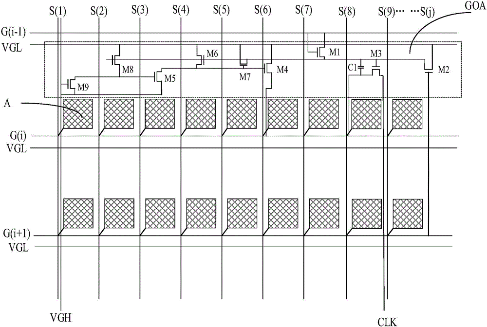
[0037] Such as figure 1As shown, this embodiment provides a display panel, which includes M gate lines and N data lines arranged crosswise, G(i) is any one of the gate lines, and 1≤i≤M; M is an integer, S(j) is any one of the data lines, and 1≤j≤N; N is an integer. The intersections of all gate lines G(i) and all data lines S(j) define a plurality of pixel units A, and the disconnection positions in the gate lines G(i) of each row are the same, and each row of gate lines G(i) Divided into multiple grid line segments g; according to the disconnection position of each row of grid line G(i), the display area of ​​the display panel is divided into a plurality of sub-display areas Q set at intervals; each grid line segment g is connected to an independent shift A register unit GOA, the shift register unit GOA is used to provide a gate scanning signal for the gate line segment g connected thereto. Wherein, the shift register units GOA in the same sub-display area Q are cascaded to...

Embodiment 3

[0048] This embodiment also provides a display panel. The structure of the display panel is similar to that of the display panel in Embodiment 2. The difference is that in the display panel of this embodiment, the grid line segments g in the same row are connected The register unit GOA, that is to say a shift register unit GOA is used to provide a gate scan signal for a row of gate line segments g.

[0049] In this embodiment, since the gate line segment g in the same row is connected to the same shift register unit GOA, it is only necessary to add a plurality of signal output terminals OUTPUT to each shift register unit GOA at this time, the process is simple, and The shift register unit GOA is set in the area where the pixel unit A is located, that is, it is set in the display area of ​​the display panel. Compared with the existing display panel in which the shift register unit GOA is set in the surrounding area, the display panel of this embodiment The borders are narrower....


PUM


Abstract

The invention provides a display panel and a display device, belongs to the display technology field, and helps to solve the problem that the frame of a conventional display panel is wide. The display panel comprises a display area and surrounding areas. The display area includes multiple grid lines and multiple data lines, the grid lines and the data lines crossing each other. The grid lines and the data lines cross each other to define multiple pixel units. At least one grid line includes at least two grid line segments that are disconnected from each other, and each grid line segment correspondingly controls at least one pixel unit. The display area is divided into at least two sub-display areas according to the disconnection positions of the grid line segments. A shift register unit connected to the grid line segments is arranged in at least one sub-display area, and is used for providing grid scan signals to the grid line segments connected to the shift register unit. At least part of the shift register units are arranged in the display area, so the frame of the display panel is narrow.

Description

technical field [0001] The invention belongs to the field of display technology, and in particular relates to a display panel and a display device. Background technique [0002] The basic principle of TFT-LCD (Thin Film Transistor-Liquid Crystal Display, thin film transistor liquid crystal display) to realize a frame display is to input a square wave of a certain width to each row of pixels sequentially from top to bottom through the gate drive. strobe, and then through the source (source) to drive the signal required for each row of pixels to be output from top to bottom in turn. At present, the display device with such a structure is usually made of gate drive circuit and source drive circuit on the glass panel by COF (Chip On Film, chip-on-film) or COG (Chip On Glass, chip directly fixed on the glass) process. However, when the resolution is high, the output of the gate drive circuit and the source drive circuit will increase, and the length of the drive circuit will als...

Claims


Application Information

Patent Timeline
Patent Type & Authority Applications(China)
IPC IPC(8): G09G3/36
Inventor 姚星林家强张玉婷张慧
Owner BOE TECH GRP CO LTD
Why Eureka
Try Eureka