Lead shielding structure of non-detection surface of scintillant

A scintillator and lead shielding technology, which is applied in shielding, radiation intensity measurement, reactors, etc., can solve the problems of destroying the direct contact between the lead plate and the scintillator, failing to ensure the same thickness of the lead plate, and affecting the performance of the detector, so as to achieve improved shielding Effect, structure design is simple and effective, and the effect of easy installation

Active Publication Date: 2015-09-23
NUCTECH CO LTD
View PDF8 Cites 4 Cited by
  • Summary
  • Abstract
  • Description
  • Claims
  • Application Information

AI Technical Summary

Problems solved by technology

[0004] Another scintillator shielding method is to fold the lead plate at the corner of the scintillator when placing the lead plate on the non-detecting side of the scintillator, although this avoids the problem of gaps at the connection between every two non-detecting surfaces , but there is no guarantee that the thickness of the lead plate at the corner of the scintillator is the same as the thickness of the lead plate at the plane. This way and the former way will affect the performance of the detector
[0005] In addition, the screw installation method of fixing the scintillator 1 by using the metal shell 2 is generally such that the metal screw 3 is perpendicular to the detection surface, such as Figure 5 As shown, this metal screw 3 installation method needs to consider the possibility that the metal screw 3 will destroy the direct contact between the lead plate and the scintillator, and the lead plate needs to avoid the metal screw during installation. The thickness of the lead plate is smaller than that of other areas, which will also affect the detector performance

Method used


Image

  • Lead shielding structure of non-detection surface of scintillant
  • Lead shielding structure of non-detection surface of scintillant
  • Lead shielding structure of non-detection surface of scintillant

Examples


Embodiment Construction

[0041] Exemplary embodiments of the present invention are described in detail below, examples of which are illustrated in the accompanying drawings, wherein the same or similar reference numerals designate the same or similar elements. The embodiments described below with reference to the figures are exemplary and are intended to explain the present invention, and should not be construed as limiting the present invention.

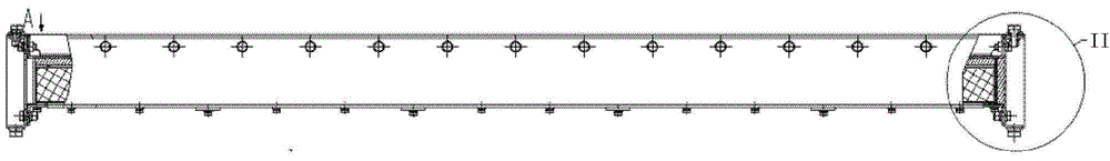
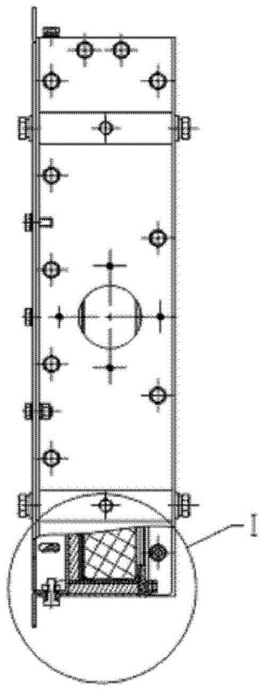
[0042] see Image 6 , the scintillator detector is approximately regarded as a cuboid, and the six sides of the scintillator detector are named, such as Image 6 As shown, the four sides are A surface, B surface, C surface, and D surface, the detection surface is E surface, and the bottom surface is F surface. Among them, A surface, B surface, C surface, D surface and F surface are non-detection surfaces. surface, shielding with lead plates is required. The two sides of C / D are symmetrical structures.

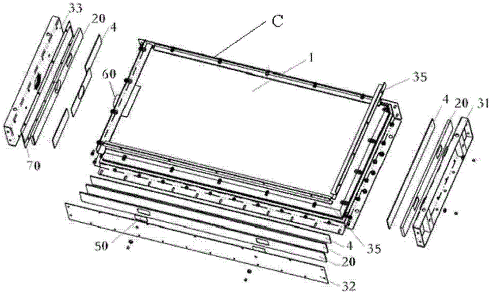
[0043] Such as Figure 7-9 As shown, the scintilla...


PUM


Abstract

The invention provides a lead shielding structure of a non-detection surface of a scintillant. The scintillant comprises a detection surface, a bottom surface opposite to the detection surface, and four side surfaces. The lead shielding structure comprises a bottom lead plate part which is arranged on the bottom surface of the scintillant, and four side surface lead plate parts which are respectively arranged on four side surfaces of the scintillant; at least one of the five lead plate parts is a stepped lead plate part of which the side edge is provided with an L-shaped step surface; the matching surface between the step surface of the stepped lead plate part and the adjacent lead plate part comprises a right angle plane. The invention also relates to a housing assembly of a scintillant detector, the scintillant detector and a radiation detection device.

Description

technical field [0001] The invention belongs to the technical field of radioactivity measurement, and in particular relates to a lead shielding structure of a scintillator non-detection surface, a shell assembly of a scintillator detector and a scintillator detector. Background technique [0002] The non-detecting surface of the scintillator in the scintillator detector must be shielded with lead, usually by using a certain thickness of lead plate outside the scintillator for shielding. [0003] Currently, a scintillator shielding method is to use a lead plate 100 of the same thickness to be pasted on each non-detecting surface of the scintillator 1, and then screw 3 through the metal shell 2 to fix it. Such a scintillator shielding method causes every two There is a gap at the connection between two non-detecting surfaces, see Figure 1-4 ,exist figure 2 , 4 Among them, there is a shock-absorbing pad 4 between the horizontal lead plate and the vertical lead plate. Obviou...

Claims


Application Information

Patent Timeline
Patent Type & Authority Applications(China)
IPC IPC(8): G21F3/00G21F1/08G01T1/20
CPCG01T1/20G21F1/08G21F3/00
Inventor 于海军包云肽张阳天钟庆霞
Owner NUCTECH CO LTD
Why Eureka
Try Eureka