Parallel thyristor circuit with overvoltage protection

A thyristor and overvoltage technology, which is applied in the field of parallel thyristor overvoltage protection circuit, can solve problems such as early triggering, large on-off current, and thyristor burnout, and achieve the effects of avoiding interference, improving consistency, and preventing false triggering

Inactive Publication Date: 2015-09-23
ZHUZHOU NAT ENG RES CENT OF CONVERTERS
View PDF4 Cites 3 Cited by
  • Summary
  • Abstract
  • Description
  • Claims
  • Application Information

AI Technical Summary

Problems solved by technology

But this method is used when the thyristors are connected in parallel. If each thyristor is equipped with a BOD transistor, the voltage applied to both ends of the thyristor and the BOD transistor is the same, but no matter how mature the manufacturing process of the BOD transistor is, the individual differences will always be Existence, it is precisely because of the difference in the performance of BOD tubes that their trigger voltages are inconsistent, which will cause one or several BODs to be triggered in advance, and the BOD tubes triggered in advance will cause their corresponding thyristors to be triggered in advance , so that all the current will pass through these thyristors triggered in advance, which may cause these thyristors to burn out due to excessive current
[0004] Due to the diversity of current circuit loads, some loads are large inductive loads, and the on-off current is large. The control of a single thyristor cannot meet the circuit requirements. Therefore, for such circuit loads, it is necessary to connect multiple thyristors in parallel to meet the current requirements.
However, there is no voltage equalization requirement for parallel thyristor circuits, because the voltage applied to both ends of each parallel thyristor is the same. If each thyristor is equipped with a BOD transistor for protection, there will be inconsistent performance of BOD transistors as described above. The problem that some thyristors are triggered early and damaged

Method used


Image

  • Parallel thyristor circuit with overvoltage protection

Examples


Embodiment Construction

[0018] The present invention will be further described below in conjunction with the accompanying drawings and specific embodiments.

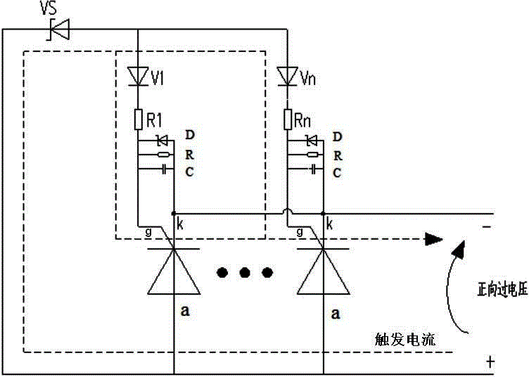
[0019] like figure 1 As shown, the parallel thyristor circuit with overvoltage protection in this embodiment includes a plurality of thyristors V1-Vn, and the plurality of thyristors are connected in parallel, that is, the anodes a of the plurality of thyristors are connected to each other, and the cathodes k of the plurality of thyristors are connected to each other, and the gates of the plurality of thyristors The pole g and the anode a are connected through a trigger element. Under normal circumstances, the trigger element presents high impedance, and the gate g of the thyristor has no current passing through, and the thyristor is in an off state. When applied to multiple thyristor anode a and cathode k When the positive voltage between exceeds the trigger voltage of the trigger element, the trigger element will turn to the on-state, and at ...


PUM

PropertyMeasurementUnit
Resistanceaaaaaaaaaa

Abstract

The invention discloses a parallel thyristor circuit with overvoltage protection. The parallel thyristor circuit comprises a plurality of thyristors, the plurality of thyristors are connected in parallel, gate electrodes of the plurality of thyristors are connected with anodes of the thyristors via trigger elements, and when the voltage between the anodes and cathodes of the plurality of thyristors reach a trigger voltage of the trigger elements, and the trigger elements are in the switch-on state. The parallel thyristor circuit with overvoltage protection is advantageous in that the circuit is simple, and the thyristors can be simultaneously triggered.

Description

technical field [0001] The invention mainly relates to the technical field of power electronics, in particular to a parallel thyristor overvoltage protection circuit. Background technique [0002] At present, two methods are generally used for overvoltage protection of thyristor components: the first method is to use a voltage detection circuit and preset the overvoltage threshold through the control system. When the voltage across the thyristor received by the control system exceeds its When the preset threshold voltage is reached, the control system sends out a trigger signal to forcibly trigger the thyristor. But this method needs to configure the control system, and is limited by the control hardware and control program, the design is complex and difficult to maintain. [0003] The second method is to use BOD (Break Over Diode), which is a breakdown diode as a protection device. This method is generally used in series thyristor circuits. In the series thyristor circuit...

Claims


Application Information

Patent Timeline
IPC IPC(8): H03K17/08
Inventor 陈洁莲张敏郭民李先强赵道德初蕊蔡宇峰许汝波田华贵孙茂陶洪亮陈元初王海军
Owner ZHUZHOU NAT ENG RES CENT OF CONVERTERS
Why Eureka
Try Eureka