A channel estimation method and device based on a demodulation reference signal

A demodulation reference signal and channel estimation technology, which is applied in channel estimation, pilot signal allocation, transmission path sub-channel allocation, etc., can solve problems such as performance inconsistency, floor effect, etc., to avoid floor effect and suppress Gibbs The effect of the jitter phenomenon

Active Publication Date: 2018-04-27
WUHAN HONGXIN TELECOMM TECH CO LTD
View PDF7 Cites 0 Cited by
  • Summary
  • Abstract
  • Description
  • Claims
  • Application Information

AI Technical Summary

Problems solved by technology

[0005] In view of this, the present application provides a channel estimation method and device based on a demodulation reference signal to overcome the problems caused by the high signal-to-noise ratio and LS The inconsistent performance of the algorithm leads to the problem of floor effect

Method used


Image

  • A channel estimation method and device based on a demodulation reference signal
  • A channel estimation method and device based on a demodulation reference signal
  • A channel estimation method and device based on a demodulation reference signal

Examples


Embodiment 1

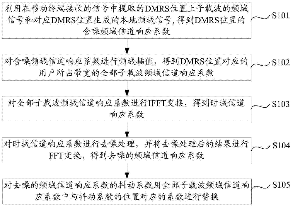
[0050]Embodiment 1 of the present application provides a channel estimation method based on a demodulation reference signal, such as figure 1 As shown, the method includes:

[0051] S101: Obtain the noisy frequency domain channel response coefficient of the DMRS position by using the frequency domain signal of the subcarrier at the DMRS position extracted from the signal received by the mobile terminal and the local frequency domain signal generated corresponding to the DMRS position.

[0052] S102: Perform frequency-domain interpolation on the noisy frequency-domain channel response coefficients to obtain frequency-domain channel response coefficients of all subcarriers in the bandwidth occupied by the user corresponding to the DMRS position.

[0053] Specifically, performing frequency-domain interpolation on the noisy frequency-domain channel response coefficients refers to performing frequency-domain interpolation on the bandwidth occupied by the DMRS. In order to facilitat...

Embodiment 2

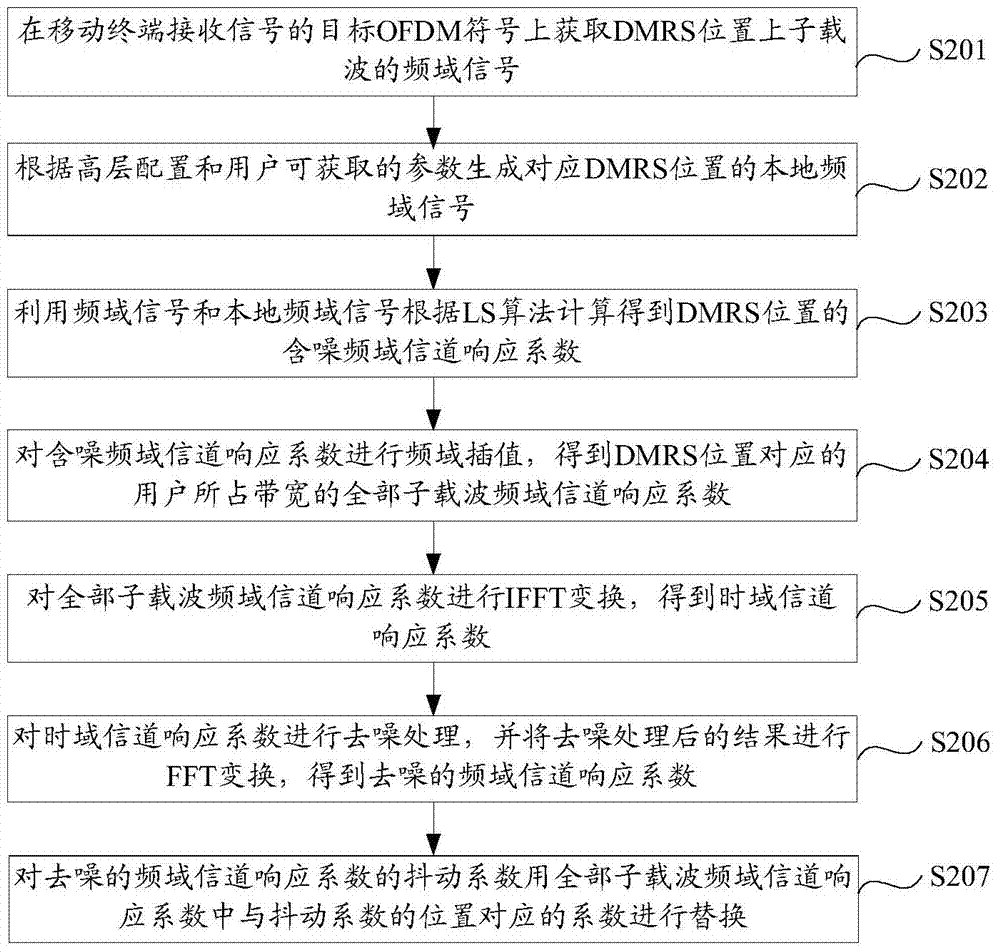
[0060] On the basis of the first embodiment, the second embodiment of the present application provides another more specific channel estimation method based on a demodulation reference signal.

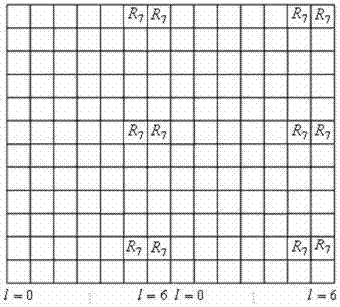
[0061] Such as figure 2 as shown, figure 2 Indicates a distribution of DMRS in the OFDM resource grid when a user is allocated a PRB bandwidth. R7 represents the RE (Resource Element, resource unit) position occupied by the DMRS, the horizontal direction represents the time axis, and the vertical direction represents the frequency axis. At this time, the user occupies 14 OFDM symbols in the time domain and 12 subcarriers in the frequency domain. Among them, the first column l=0 means OFDM symbol 0, and there are 14 columns in total, that is, 14 OFDM symbols. The 7 consecutive OFDM symbols on the left form a PRB, and the 7 consecutive OFDM symbols on the right are also a PRB. Occupies 12 subcarriers.

[0062] What needs to be clear is that the basic principle of the LS algorithm: ...

Embodiment 3

[0100] On the basis of the first embodiment of the present application, the third embodiment of the present application provides a channel estimation device corresponding to the channel estimation method described in the first embodiment. Such as Figure 4 as shown, Figure 4 It is a schematic structural diagram of an apparatus for channel estimation based on a demodulation reference signal provided in Embodiment 3 of the present application. The device includes: an acquisition unit 301, an interpolation unit 302, a first transformation unit 303, a denoising unit 304, a second transformation unit 305, and a replacement unit 306, wherein,

[0101] The acquisition unit 301 is configured to obtain the noisy frequency domain channel response coefficient of the DMRS position by using the frequency domain signal of the subcarrier at the DMRS position extracted from the signal received by the mobile terminal and the local frequency domain signal generated corresponding to the DMRS p...


PUM


Abstract

The invention provides a channel estimation method and device based on a demodulation reference signal. The method comprises the steps of acquiring noisy frequency domain channel response coefficients of a demodulation reference signal (DMRS) position, and performing frequency domain interpolation on the noisy frequency domain channel response coefficients, so as to obtain all sub-carrier frequency domain channel response coefficients of user occupied bandwidth corresponding to the DMRS position; performing inverse fast fourier transform (IFFT) on the all sub-carrier frequency domain channel response coefficients, so as to obtain time domain channel response coefficients; performing de-noising processing on the time domain channel response coefficients, and then performing fast fourier transform (FFT), so as to obtain denoised frequency domain channel response coefficients; and replacing jitter coefficients of the denoised frequency domain channel response coefficients. According to the method, as frequency domain interpolation is performed on the noisy frequency domain channel response coefficients, all sub-carrier frequency domain channel response coefficients of user occupied bandwidth corresponding to the DMRS position are acquired; and the jitter coefficients of the denoised frequency domain channel response coefficients are replaced, so that Gibbs jitter phenomenon is prevented, and the floor effect is prevented to occur.

Description

technical field [0001] The present application relates to the field of communication technology, and in particular to a channel estimation method and device based on a demodulation reference signal. Background technique [0002] LTE-A (Long Term Evolution-Advanced, Long Term Evolution Enhancement), as an enhanced technology of LTE, continues to use OFDM (Orthogonal Frequency Division Multiplexing, Orthogonal Frequency Division Multiplexing) and multi-antenna (MIMO) technology as the core technology of the physical layer. [0003] In the current LTE-A system, a channel estimation algorithm based on DFT (Discrete Fourier Transform, Discrete Fourier Transform) is generally used to extract the reference signal information on an OFDM symbol, and then perform LS (Least square, least square) channel estimation. Estimate, perform IFFT (Inverse Fast Fourier Transform, inverse Fast Fourier Transform) on the estimated result to obtain the channel time domain response coefficient, and p...

Claims


Application Information

Patent Timeline
Patent Type & Authority Patents(China)
IPC IPC(8): H04L25/02H04L5/00
CPCH04L5/0048H04L25/0202
Inventor 王亚林张元雨
Owner WUHAN HONGXIN TELECOMM TECH CO LTD
Why Eureka
Try Eureka