Splicer

A technology of splicing parts and electrical connectors, applied in entertainment, toys, etc., can solve the problems of inability to splice graphics, practical and interesting bottlenecks of electronic building blocks, and inability to create splicing methods, so as to achieve rich and diverse splicing methods Sexual, easy splicing effect

Active Publication Date: 2015-09-30
SHENZHEN BOYUE DOMESTIC GOODS
View PDF8 Cites 9 Cited by
  • Summary
  • Abstract
  • Description
  • Claims
  • Application Information

AI Technical Summary

Problems solved by technology

However, the current electronic splicing pieces are usually provided with connectors on one or both sides (mainly composed of spring probe POGO PIN), the connection method between the connecting blocks is relatively simple, and it is impossible to create more splicing methods , and it is impossible to stitch together rich graphics, which is also the practical and interesting bottleneck of electronic building blocks

Method used


Image

  • Splicer
  • Splicer
  • Splicer

Examples


Embodiment 1

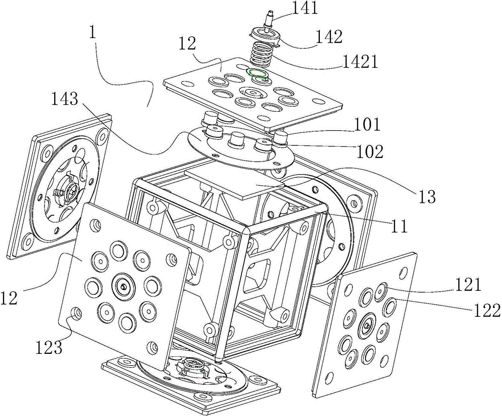
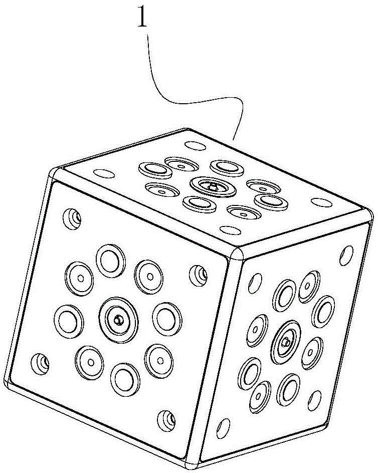
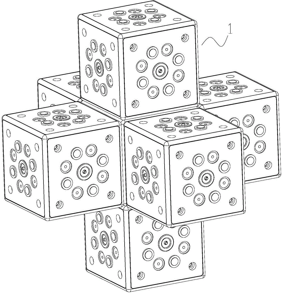
[0042] Embodiment one, such as figure 1 , 2 , 3 shown. In this embodiment, the splicing piece includes several independent identical cube blocks 1, and the magnetic components on each surface of the block 1 are composed of four magnetic blocks 101 and four magnetic metals 102 arranged at intervals in sequence. , one of the preferred layout methods see Figure 10 Schematic: each magnetic block 101 and magnetic metal 102 are not placed on the center line of the square surface 12 of the block (this ensures that the mirror image principle can be used correctly to realize the mutual interaction between the magnetic block and the magnetic metal on different block surfaces. Matching), each magnetic block 101 and the center point where the magnetic metal 102 is placed are sequentially connected to an octagon concentric with the square surface 12 of the block (including but not limited to a regular octagon, other octagons that meet the conditions It can also be realized), the octago...

Embodiment 2

[0048] Embodiment two, such as Figure 4 , 5 , 6 shown. In this embodiment, the splicing piece includes several independent identical cube blocks 2, and the magnetic attraction assembly on each face of the block 2 includes a fool-proof structure and a radial filling that is concentrically arranged with the square surface of the block. Magnetic ring magnet 20, after the ring magnet 20 is radially magnetized, the magnetism on its surface is S-N relationship. Installed on the square surface of the block 2; when the two faces of the two blocks are close together, as if the side is an N-S pole, the ring magnet 20 is mutually repulsive, and at this time the ring magnet 20 will be on the plastic cover 22 Rotate in the cavity 24, self-adjust to the position where the magnetic poles attract each other.

[0049] The fool-proof structure is to prevent the phenomenon that the four sides of the blocks do not overlap during the stacking process. The optimal design of the fool-proof struc...

Embodiment 3

[0054] Embodiment three, such as Figure 7 , 8 , as shown in 9. In this embodiment, the splicing piece includes several independently identical cube blocks 3, and the magnetic assembly on each face of the block 3 is composed of four magnetic blocks 30 and a magnetic metal ring sheet 343; The center point of block 30 is evenly distributed on a circle with the center point of the block square surface 32 as the center of the circle, as Figure 11 As shown, none of the magnetic blocks 30 can be located on the centerline and diagonal of the square surface 32 of the block (this ensures that the mirror image principle can be used correctly to prevent the correspondence between the magnetic block and the magnetic block), each block on each block The polarity and setting positions of the four magnetic blocks facing the surface are the same, for example, all magnetic blocks 30 are N poles facing outside the surface of the block, and S poles are facing in the block; or, all magnetic bl...


PUM


Abstract

The invention discloses a spliced part. The spliced part comprises a plurality of splicing blocks. Each splicing block is a cube with six surfaces, wherein identical magnetic assemblies are arranged on the six surfaces. Any two surfaces of any one splicing block and any two surfaces of another splicing block can be spliced through attractive force of the magnetic assemblies in a four-side-coinciding mode. According to the spliced part, the cubic splicing blocks are adopted, the magnetic assemblies are arranged on all surfaces of each splicing block, the six surfaces of each splicing block can be spliced with the surfaces of other splicing blocks in all directions through the attractive force, the splicing methods are various, various shapes can be spliced, splicing can be achieved more easily due to the magnetic method, and the spliced part is more interesting. The spliced part is an unparalleled innovation in the field of spliced parts and has great market prospect.

Description

[0001] This case is the second divisional application of the invention patent No. 201310395142.8 "a splicing piece" filed on September 3, 2013. technical field [0002] The present invention relates to the technical field of splicing pieces, especially toy splicing pieces, such as plastic building blocks, electronic building blocks, etc. Of course, this technology is also widely applicable to non-toy application technical fields of quick assembly and disassembly and various splicing. Background technique [0003] The current splicing parts are mainly used in children's toys in large quantities, such as plastic building blocks, electronic building blocks, etc. They have a common feature, that is, they can be installed and disassembled quickly and easily, and can be spliced ​​into various shapes. On the market, disassembly and assembly are mainly realized by the connection and occlusion of mechanical structures. The connection method between the splicing parts of this prior ar...

Claims


Application Information

Patent Timeline
Patent Type & Authority Applications(China)
IPC IPC(8): A63H33/26A63H33/08
Inventor 魏正鹏
Owner SHENZHEN BOYUE DOMESTIC GOODS
Why Eureka
Try Eureka