
multi-faceted electronic building blocks

A technology of electronic building blocks and surface contact, applied in toys, instruments, entertainment, etc., can solve the problems of inability to create splicing methods, splicing graphics, practical and interesting bottlenecks of electronic building blocks, etc., and achieve rich and diverse splicing methods. Educational significance, effect of enriching diversity

Active Publication Date: 2016-08-10
SHENZHEN BOYUE DOMESTIC GOODS
View PDF11 Cites 0 Cited by
  • Summary
  • Abstract
  • Description
  • Claims
  • Application Information

AI Technical Summary

Problems solved by technology

However, the current electronic splicing pieces are usually provided with connectors on one or both sides (mainly composed of spring probe POGO PIN), the connection method between the connecting blocks is relatively simple, and it is impossible to create more splicing methods , and it is impossible to stitch together rich graphics, which is also the practical and interesting bottleneck of electronic building blocks

Method used


Image

  • multi-faceted electronic building blocks
  • multi-faceted electronic building blocks
  • multi-faceted electronic building blocks

Examples


Embodiment 1

[0025] Embodiment one, such as Figure 5 shown. In this embodiment, inner cavities 1121 are provided at both ends of the splicing boss 11 ; A positioning column 1122 matched with the ring of the ring magnet 1120 is also provided in the inner cavity 1121, and the ring magnet 1120 can rotate freely around the axial direction; after the ring magnet 1120 is radially magnetized, the The magnetism is an S-N relationship. When the two faces of the two blocks are close together, as if the sides are N-S poles, the ring-shaped magnets 1120 are mutually repulsive. At this time, the ring-shaped magnets 1120 will rotate in the inner cavity 1121. Self-adjust to the position where the magnetic poles attract each other.

Embodiment 2

[0026] Embodiment two, such as Image 6 shown. In this embodiment, inner cavities 1121 are provided at both ends of the splicing boss 11 ; the magnetic attraction assembly includes radially magnetized magnets movable in the inner cavities, and the magnets are spherical magnets 1123 . The spherical magnet 1123 can rotate freely; after the radial magnetization of the spherical magnet 1123, the magnetism on its surface is an S-N relationship. At this time, the spherical magnet 1123 will rotate in the inner cavity 1121 and adjust itself to a position where the magnetic poles attract each other.

Embodiment 3

[0027] Embodiment three, such as Figure 7 shown. In this embodiment, inner cavities 1121 are provided at both ends of the splicing boss 11; Cylindrical magnet 1124 can rotate freely around the axial direction; the magnetism on the surface of cylindrical magnet 1124 after radial magnetization is S-N relationship. The magnets 1124 are mutually repulsive. At this time, the cylindrical magnet 1124 will rotate in the inner cavity 1121 and adjust itself to a position where the magnetic poles attract each other.

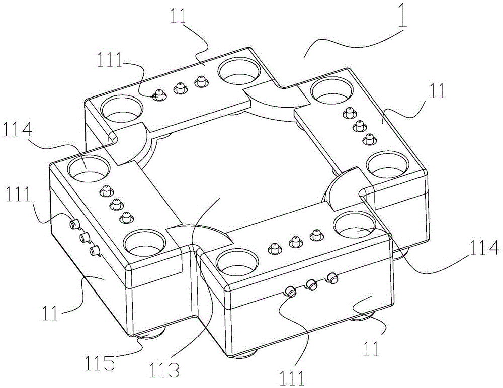
[0028] combine Figure 8 with 9 The structure of the electrical connector in the specific embodiment will be described in detail. The electrical connector 111 is at least one connection contact on the outer side and the upper end surface of the splicing boss 11, and in a preferred embodiment, it is three connection contacts, and the connection contacts are spring probes or shrapnel; The connecting piece 111 is at least one contact end on the lower end surface of the s...


PUM


Abstract

The invention discloses a multi-faceted contact electronic building block, which comprises a plurality of identical blocks with a cross-shaped structure, four identical splicing bosses, and internal devices with circuit boards and electronic components; the outer surfaces of the splicing bosses and The upper and lower end faces are provided with electrical connectors connected to the circuit board; the electrical connectors are connected in parallel to each other and can be used to transmit current, signal or data; the splicing boss is equipped with a magnetic attraction component, and the splicing boss surface can pass through the magnetic attraction The components are attracted and spliced ​​together and the electrical connectors can be conducted. This scheme adopts a cross-shaped block, which has twelve faces that can be spliced ​​by magnetic attraction to the outside. The board and electronic components realize the function of electronic building blocks. The structure of the electrical connector ensures that when the block is adsorbed on different sides and at different angles, it can stably conduct current, transmit data or signals, etc. This scheme greatly enriches the diversity and interest of the splicing shapes of electronic building blocks, and has excellent educational significance and huge market value.

Description

technical field [0001] The present invention relates to the technical field of splicing pieces, especially toy splicing pieces, such as plastic building blocks, electronic building blocks, etc. Of course, this technology is also widely applicable to non-toy application technical fields of quick assembly and disassembly and various splicing. Background technique [0002] The current splicing parts are mainly used in children's toys in large quantities, such as plastic building blocks, electronic building blocks, etc. They have a common feature, that is, they can be installed and disassembled quickly and easily, and can be spliced ​​into various shapes. On the market, disassembly and assembly are mainly realized by the connection and occlusion of mechanical structures. The connection method between the splicing parts of this prior art is relatively primitive, most of the splicing is laborious and the splicing stability is not good, it is impossible to create more splicing meth...

Claims


Application Information

Patent Timeline
Patent Type & Authority Patents(China)
IPC IPC(8): A63H33/26A63H33/06G09B23/18
Inventor 魏正鹏
Owner SHENZHEN BOYUE DOMESTIC GOODS
Learn More