An injection molding machine injection system

An injection system and injection molding machine technology, applied in the field of injection molding machine injection system, can solve problems such as barrel and screw movement deviation, operation deviation, increase energy consumption and cost, achieve low energy consumption and cost, improve injection precision, simple structure

Active Publication Date: 2018-10-09
NINGBO SHUANGSHENG PLASTIC MACHINERY
View PDF7 Cites 0 Cited by
  • Summary
  • Abstract
  • Description
  • Claims
  • Application Information

AI Technical Summary

Problems solved by technology

[0003] For example, the invention patent with the application number 200710069995.7 discloses an injection mechanism of an injection molding machine, and discloses technical features such as the injection platform support, the injection platform front plate, the injection platform rear plate, the injection cylinder group, and the translation cylinder group. A barrel is installed on the front plate of the injection platform, and a screw is installed in the barrel, and the screw is fixedly connected with the rear plate of the injection platform. The moving oil cylinder group can move the front plate of the injection platform on the support of the injection platform, so that the barrel is close to the mold, and the injection The oil cylinder group can move the back plate of the injection platform on the support of the injection platform, and push the screw to move in the barrel to perform injection. This traditional injection mechanism has the following technical problems. 1. The use of two oil cylinder groups increases the use of Energy consumption and cost, 2. Two oil cylinder groups make the injection mechanism more complex in structure, and there is a certain deviation during operation, which causes a large deviation when the barrel and the screw move, which greatly affects the injection accuracy of the entire injection mechanism

Method used


Image

  • An injection molding machine injection system
  • An injection molding machine injection system
  • An injection molding machine injection system

Examples


Embodiment Construction

[0027] The following are specific embodiments of the present invention and in conjunction with the accompanying drawings, the technical solutions of the present invention are further described, but the present invention is not limited to these embodiments.

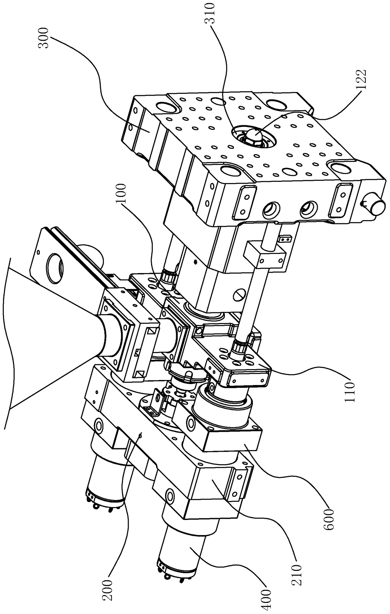
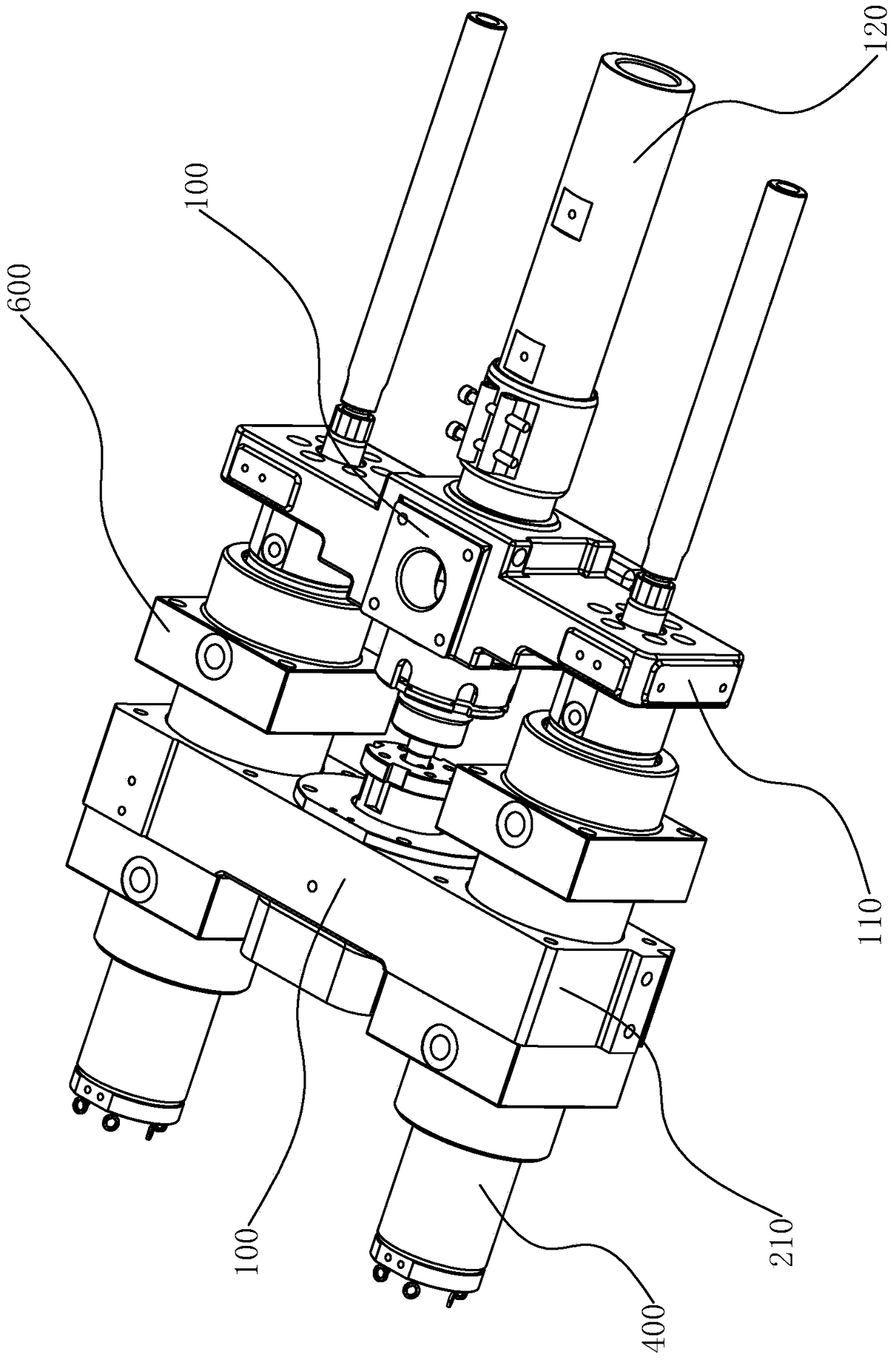
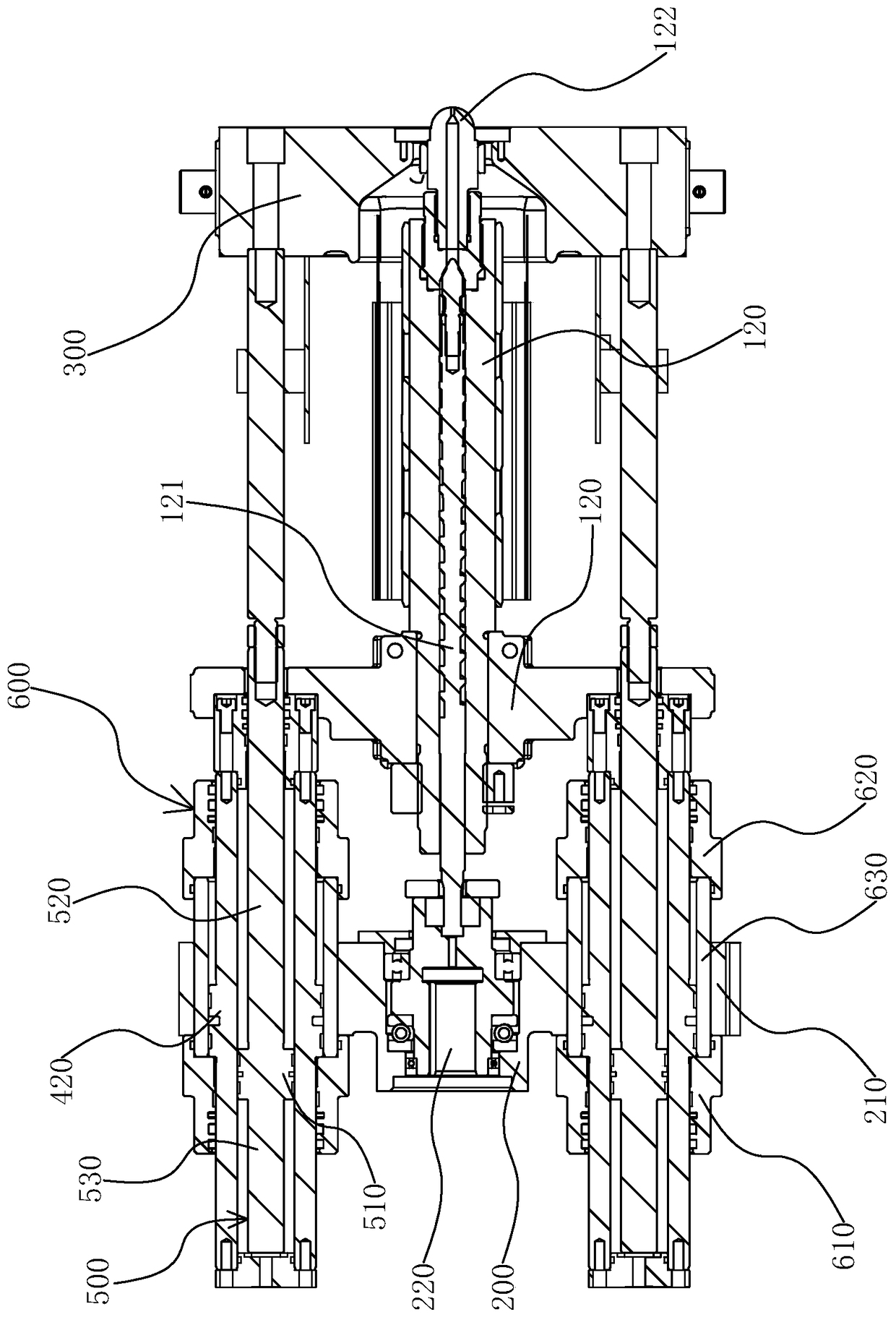
[0028] like Figure 1 to Figure 3 As shown, an injection system of an injection molding machine includes a fixed base 100 , a movable base 200 and a fixed plate 300 , and the fixed base 100 is located between the movable base 200 and the fixed plate 300 .

[0029] Fixing plates 110 are respectively extended from both sides of the fixing seat 100, and a barrel 120 is axially installed on the fixing seat 100. The barrel 120 runs through the fixing seat 100 and is fixedly connected with the fixing seat 100. A screw 121 is arranged in the barrel 120, and the barrel 120 The front end of 120 is provided with injection nozzle 122 .

[0030] The mobile base 200 is located behind the barrel 120 and is separated from the fixed seat...


PUM


Abstract

The invention provides an injection system of an injection molding machine and belongs to the technical filed of injection molding machines. The technical problem that an existing injection molding machine is high in energy consumption and cost and relative low in injection precision is solved. The technical scheme is as follows: the injection system of the injection molding machine comprises a stationary base, a mobile base and two piston components, wherein a material cylinder is arranged on the stationary base, and a screw is arranged in the material cylinder; the mobile base is connected with the screw and drives the screw to rotate in the material cylinder; the two piston components are arranged at two sides of the mobile base respectively and are connected with the stationary base; the mobile base is separately connected with the two piston components; the piston components can drive the stationary base to move back and forth and drive the mobile base to move, so that the screw moves in the material cylinder. Through one piston component, both the material cylinder and the screw can move and the injection purpose is realized; compared with a traditional injection mechanism, the injection system is simple in structure and low in energy consumption and cost.

Description

technical field [0001] The invention belongs to the technical field of injection molding machines, and relates to an injection system of an injection molding machine. Background technique [0002] The injection molding machine is mainly composed of a mold opening and closing system, a mold adjustment system and an injection system. The mold opening and closing system determines the important performance parameter of the injection molding machine - the clamping force, while the injection system plays an important role in the injection accuracy and injection quality of the injection molding machine. key role. [0003] For example, the invention patent with the application number 200710069995.7 discloses an injection mechanism of an injection molding machine, and discloses technical features such as the injection platform support, the injection platform front plate, the injection platform rear plate, the injection cylinder group, and the translation cylinder group. A barrel is...

Claims


Application Information

Patent Timeline
Patent Type & Authority Patents(China)
IPC IPC(8): B29C45/54
CPCB29C45/531B29C2045/548
Inventor 于春雷
Owner NINGBO SHUANGSHENG PLASTIC MACHINERY
Why Eureka
Try Eureka