Magnetic bearing, shaft and shaft mounting

A technology of magnetic bearings and permanent magnets, applied in shafts and bearings, magnetic bearings, bearings, etc., can solve problems such as large tolerance movement, and achieve the effects of small current heat loss, uniform flux density distribution, and minimized eddy current loss

Active Publication Date: 2015-09-30
RIETER CZ AS
View PDF13 Cites 5 Cited by
  • Summary
  • Abstract
  • Description
  • Claims
  • Application Information

AI Technical Summary

Problems solved by technology

However, the radial position of the shaft and spi

Method used


Image

  • Magnetic bearing, shaft and shaft mounting
  • Magnetic bearing, shaft and shaft mounting
  • Magnetic bearing, shaft and shaft mounting

Examples


Embodiment Construction

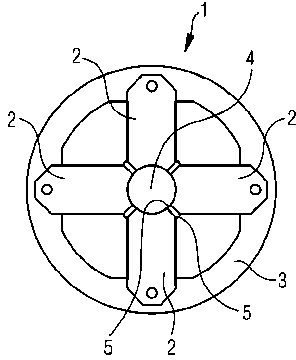
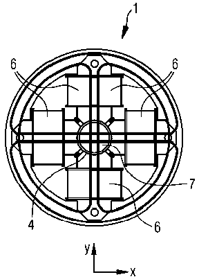
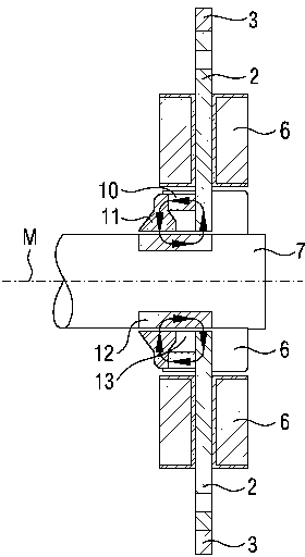
[0049] exist figure 1 A stator 1 is shown in , which has four pole cores 2 which are connected to each other as a stator cross structure. Arranged at the outer end of the pole core 2 is a stator ring 3 which surrounds all the pole cores 2 . At the other end of the pole core 2 there is provided an opening 4 which can receive a shaft (not shown here). The pole cores 2 are connected to one another at their inner ends by means of saturated webs 5 . The first saturated web 5 is arranged in the vicinity of the opening 4 , while the second saturated web 5 is arranged at a greater distance from the opening 4 . In each case two saturation bridges 5 connect two adjacent pole cores 2 . The saturating webs 5 are designed in such a way that the coil flux essentially does not flow through the saturating webs 5 or adjacent pole cores arranged therebetween, but instead flows through the shaft which is then arranged in the opening 4 . The pre-magnetizing flux through the permanent magnet w...


PUM


Abstract

A magnetic bearing for the mounting of a shaft (7), in particular for a spinning rotor of an open-end spinning device, features several pole shanks (2) of a stator (1) for the active radial magnetic mounting of the shaft (7) in two degrees of freedom, which in each case are surrounded by a coil (6) and are radially arranged to each other, whereas the pole shanks (2) are arranged at each other in such a manner that they release an opening (4) for the shaft (7). In the area of the opening (4), and on the side of the coils (6) turned away from the opening (4), the pole shanks (2) are connected to each other. In particular, for the passive axial mounting of the shaft (7), at least one permanent magnet (10) is arranged between the coils (6) and the opening (4); this is in operative connection with the pole shanks (2). A shaft (7) for mounting with at least one corresponding magnetic bearing is a composite component, which at least partially consists of non ferromagnetic material. In the area of the radial and (if applicable) axial mounting, a component made of a ferromagnetic material is arranged. A shaft mounting, in particular for a rotatable shaft of a spinning rotor in an open-end spinning device, features, for the passive axial mounting of one degree of freedom of the shaft (7) and for the active radial mounting of two degrees of freedom of the shaft (7), at least one, preferably two, corresponding magnetic bearings.

Description

technical field [0001] The invention relates to a magnetic bearing for supporting the shaft of a spinning rotor, in particular for an open-end spinning machine, said magnetic bearing having a plurality of stators for active radial magnetic support of the shaft with two degrees of freedom Radially arranged pole cores (Polschenkel), which are each surrounded by a coil, wherein the pole cores are arranged in such a way that they expose an opening for a shaft, and the invention relates to a method for using at least one corresponding magnet A shaft supported by a bearing, and a bearing arrangement having such a magnetic bearing, in particular for a rotatable shaft of a spinning rotor in an air spinning spinning machine. Background technique [0002] A rotor drive for an open-end spinning device is known from DE 10 2006 053 734 A1. The rotor drive drives the shaft and the spinning rotor arranged on the shaft. The shaft is part of the rotor of the rotor drive and is magnetically...

Claims


Application Information

Patent Timeline
IPC IPC(8): F16C32/04D01H4/12H02K7/09
CPCF16C32/048F16C32/0487F16C32/0465F16C32/047F16C2340/18D01H4/12
Inventor 米兰·莫拉维克J·斯罗彭斯基齐格弗里德·西尔柏安德里亚斯·约瑟夫·普罗尔彼得·迪恩贝格尔
Owner RIETER CZ AS
Why Eureka
Try Eureka