Refrigeration system of refrigerator and refrigerator having same

A refrigeration system and refrigerator technology, applied in refrigeration and liquefaction, refrigerators, household refrigerators, etc., can solve the problems of uneven temperature, large amount of frost in the freezer, and large energy consumption of refrigerators, and achieve uniform temperature and refrigeration. Uniform, low energy consumption

Inactive Publication Date: 2015-09-30
HEFEI MIDEA REFRIGERATOR CO LTD +1
9 Cites 1 Cited by

AI-Extracted Technical Summary

Problems solved by technology

[0002] In the refrigerator in the related art, the amount of frosting in the freezer is larg...

Abstract

The invention discloses a refrigeration system of a refrigerator and the refrigerator having the same. The refrigeration system of the refrigerator comprises a compressor, multiple screw tube evaporators, multiple wound tube evaporators and a condenser, wherein the multiple screw tube evaporators are serially connected in sequence; the multiple wound tube evaporators are serially connected in sequence; and the compressor, the condenser, the multiple screw tube evaporators and the multiple wound tube evaporators are serially connected in sequence to form a cooling loop. The refrigeration system of the refrigerator according to the embodiment of the invention has such advantages as uniform refrigeration and low energy consumption.

Application Domain

Technology Topic

Image

  • Refrigeration system of refrigerator and refrigerator having same
  • Refrigeration system of refrigerator and refrigerator having same
  • Refrigeration system of refrigerator and refrigerator having same

Examples

  • Experimental program(1)

Example Embodiment

[0022] Embodiments of the present invention are described in detail below, examples of which are shown in the drawings, wherein the same or similar reference numerals designate the same or similar elements or elements having the same or similar functions throughout. The embodiments described below by referring to the figures are exemplary and are intended to explain the present invention and should not be construed as limiting the present invention.
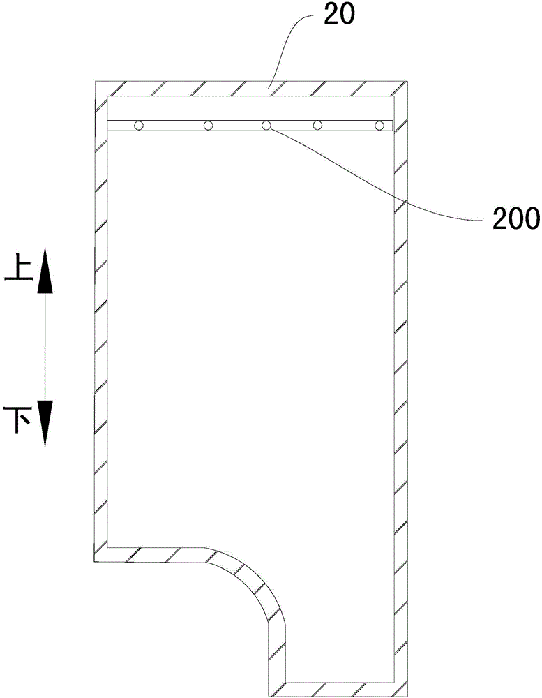
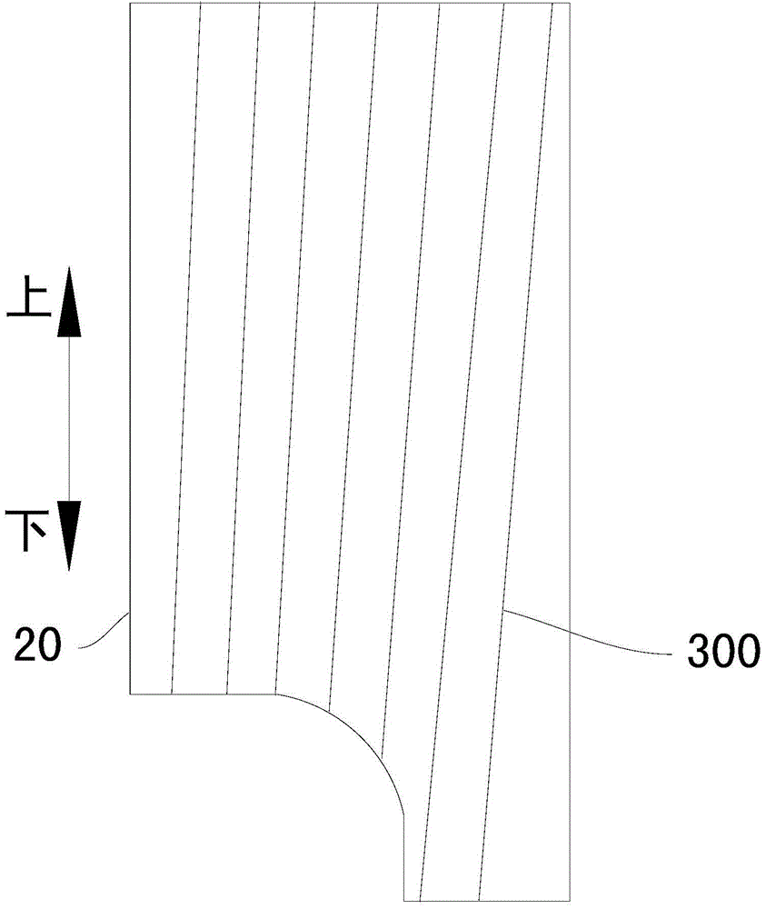
[0023] Refer below Figure 1-Figure 3 A refrigerator according to an embodiment of the present invention will be described.
[0024] like Figure 1-Figure 3 As shown, the refrigerator according to the embodiment of the present invention includes a refrigeration system 1 and a cabinet.
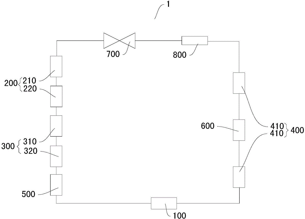
[0025] first reference figure 1 A refrigeration system 1 of a refrigerator according to an embodiment of the present invention will be described.
[0026] like figure 1 As shown, a refrigeration system 1 for a refrigerator according to an embodiment of the present invention includes a compressor 100 , a plurality of wire tube evaporators 200 , a plurality of coiled tube evaporators 300 and a condenser 400 .
[0027] Multiple wire tube evaporators 200 are connected in series, multiple coiled tube evaporators 300 are connected in series, and compressor 100, condenser 400, multiple wire tube evaporators 200 and multiple coiled tube evaporators 300 are connected in series to form a cooling circuit.
[0028] Wherein, the box body includes a plurality of freezing chambers 20, each of at least two freezing chambers 20 is provided with a silk tube evaporator 200 and a coiled tube evaporator 300 is wound on the outer wall of the inner container.
[0029] According to the refrigerator of the embodiment of the present invention, by setting the silk tube evaporator 200 in each of the at least two freezing chambers 20, the outer wall surface of the inner container of each of the at least two freezing chambers 20 is wound with a coiled tube Evaporator 300. Therefore, cooling capacity can be transferred to at least two freezer compartments 20 through the silk tube evaporator 200 and the coiled tube evaporator 300 at the same time, which can not only ensure the cooling effect of the freezer compartment 20 where it is located, but also because the coiled tube evaporator 300 is not easy to frost, it is different from the coiled tube evaporator 300 Compared with a refrigerator that only uses the silk tube evaporator 200 for refrigeration, the amount of frosting in the freezing chamber 20 is less, thereby preventing the frosting from affecting the cooling effect of the freezing chamber 20 and improving the reliability of the refrigerator.
[0030] Moreover, by setting the wire tube evaporator 200 and the coiled tube evaporator 300 in the freezer compartment 20 at the same time, the wire tube evaporator 200 can be arranged in a region where the temperature of the freezer compartment 20 is relatively high when cooling is performed only by the coiled tube evaporator 300 , Compared with the refrigerator that only uses the coiled tube evaporator 300 for refrigeration, the temperature in the freezing chamber 20 is more uniform, so that the temperature difference in the freezing chamber 20 can be reduced, and the energy consumption of the refrigerator can be reduced.
[0031] Therefore, the refrigerator according to the embodiment of the present invention has the advantages of uniform temperature in the freezing chamber and low energy consumption.
[0032] According to the refrigeration system 1 of the refrigerator according to the embodiment of the present invention, by setting a plurality of wire tube evaporators 200 connected in series and a plurality of coiled tube evaporators 300 connected in series, the wire tube evaporators 200 can be installed in the freezer compartment 20 at the same time. and the coiled tube evaporator 300, so that the silk tube evaporator 200 and the coiled tube evaporator 300 are used for cooling simultaneously. Since the compressor 100, the condenser 400, the plurality of wire tube evaporators 200 and the plurality of coiled tube evaporators 300 are sequentially connected in series to form a cooling circuit. The cooling liquid can first pass through multiple wire tube evaporators 200 for heat exchange, and then pass through multiple coiled tube evaporators 300 for heat exchange, so that the cooling effect of each wire tube evaporator 200 can be improved. Since the wire tube evaporator 200 is arranged in a region with a higher temperature in the freezer compartment 20, improving the cooling effect of the wire tube evaporator 200 can further facilitate the reduction of the temperature in the higher temperature region of the freezer compartment 20, thereby making the temperature in the freezer compartment 20 more uniform, and further reduce the energy consumption of the refrigerator.
[0033] Therefore, the refrigeration system 1 of the refrigerator according to the embodiment of the present invention has the advantages of uniform refrigeration and low energy consumption.
[0034] A refrigeration system 1 of a refrigerator according to a specific embodiment of the present invention will be described below with reference to the accompanying drawings.
[0035] In some specific embodiments of the present invention, such as figure 1 As shown, a refrigeration system 1 for a refrigerator according to an embodiment of the present invention includes a compressor 100 , a plurality of wire tube evaporators 200 , a plurality of coiled tube evaporators 300 and a condenser 400 .
[0036] The refrigerating system 1 of the refrigerator further includes a refrigerating evaporator 500 , and the refrigerating evaporator 500 is connected in series between a plurality of coiled tube evaporators 300 and the compressor 100 . In this way, the refrigerating chamber of the refrigerator can be refrigerated through the refrigerating evaporator 500. Since the refrigerating chamber requires less cooling than the freezing chamber, the refrigerant first passes through a plurality of wire tube evaporators 200 and a plurality of coiled tube evaporators 300. Furthermore, the cooling effect of the wire tube evaporator 200 and the coiled tube evaporator 300 can be guaranteed by the refrigeration evaporator 500 , so as to ensure the cooling effect of the freezing chamber 20 .
[0037] Of course, the refrigerating evaporator 500 can also be arranged in other positions of the cooling circuit according to different demands on the cooling effect. For example, if the cooling effect of the refrigeration evaporator 500 needs to be improved, the refrigeration evaporator 500 can be connected in series between multiple wire tube evaporators 200 and multiple coiled tube evaporators 300 .
[0038] Specifically, such as figure 1 As shown, the condenser 400 includes a plurality of sub-condensers 410 connected in series. Therefore, multiple sub-condensers 410 can be used for condensation, so as to increase the total area of ​​the condenser 400 , thereby ensuring the condensation effect of the condenser 400 . Specifically, there may be two sub-condensers 410 and they are respectively arranged on the left and right sides of the refrigerator.
[0039] Advantageously, as figure 1 As shown, anti-dew pipes 600 are connected in series between at least two sub-condensers 410 among the plurality of sub-condensers 410 . Thus, the anti-dew pipe 600 can be used to dissipate heat, preventing the water vapor in the refrigerator from condensing into water droplets.
[0040] Optionally, as in figure 1 As shown, a dry filter 700 and a throttling tube 800 are connected in series between the condenser 400 and the plurality of wire tube evaporators 200, and the dry filter 700 and the throttling tube 800 are connected in series. Thus, the dry filter 700 can be used to filter the solid impurities in the cooling circuit to prevent impurities from clogging the pipeline, so as to ensure the normal operation of the cooling circuit, and the throttle tube 800 is used to reduce the refrigerant pressure in the cooling circuit before entering The wire tube evaporator 200 and the coiled tube evaporator 300 are used to ensure the normal cooling of the wire tube evaporator 200 and the coiled tube evaporator 300.
[0041] Optionally, as in figure 1 As shown, the coiled tube evaporators 300 and the wire tube evaporators 200 have the same number. In this way, each freezing chamber 20 is provided with a silk tube evaporator 200 and a coiled tube evaporator 300 , thereby ensuring uniform temperature in each freezing chamber 20 .
[0042] Among them, such as figure 1As shown, both the coiled tube evaporator 300 and the wire tube evaporator 200 are connected in series. Therefore, the silk tube evaporator 200 and the coiled tube evaporator 300 can be provided in each of the two freezing compartments 20 , so that the refrigeration system 1 of the refrigerator is suitable for a refrigerator with two freezing compartments 20 .
[0043] Specifically, the two wire tube evaporators 200 include a first wire tube evaporator 210 and a second wire tube evaporator 220 , and the outlet of the first wire tube evaporator 210 is connected to the inlet of the second wire tube evaporator 220 . The two coiled tube evaporators 300 include a first coiled tube evaporator 310 and a second coiled tube evaporator 320, the outlet of the second coiled tube evaporator 220 is connected to the inlet of the first coiled tube evaporator 310, and the first coiled tube evaporator 310 The outlet of the device 310 is connected with the inlet of the second coiled evaporator 320, the outlet of the second coiled evaporator 320 is connected with the inlet of the refrigerating evaporator 500, the outlet of the refrigerating evaporator 500 is connected with the inlet of the compressor 100, and the condenser The inlet of 400 is connected with the outlet of compressor 100, the outlet of condenser 400 is connected with the inlet of drier filter 700, the outlet of drier filter 700 is connected with the inlet of throttle tube 800, the outlet of throttle tube 800 is connected with the first wire The inlet of the tube evaporator 210 is connected.
[0044] A refrigerator according to a specific embodiment of the present invention will be described below with reference to the accompanying drawings.
[0045] In some specific embodiments of the present invention, such as Figure 1-Figure 3 As shown, the refrigerator according to the embodiment of the present invention includes a refrigeration system 1 and a cabinet.
[0046] The wire tube evaporator 200 is disposed on the upper part of the corresponding freezing compartment 20 . Due to the sinking of the cold air, when only the coiled tube evaporator 300 is refrigerated and the coiled tube evaporator 300 is evenly wound outside the inner container of the freezer compartment 20, the temperature of the upper part of the freezer compartment is relatively high. Being arranged at the upper part of the freezing chamber 20 can facilitate lowering the temperature of the upper part, thereby making the temperature in the freezing chamber 20 more uniform.
[0047] Specifically, if the temperature in other regions of the freezing chamber 20 is relatively high, the silk tube evaporator 200 may also be located in this region to reduce the temperature in this region, thereby making the temperature in the freezing chamber 20 uniform. For example, the coiled tube evaporator 300 may be wound around the upper portion of the freezing compartment 20 and the wire tube evaporator 200 may be provided at the lower portion of the freezing compartment 20 .
[0048] Advantageously, the silk tube evaporator 200 and the coiled tube evaporator 300 correspond to the freezing compartment 20 respectively, and the upper part of each freezing compartment 20 is provided with a silk tube evaporator 200 , and the inner and outer tanks of each freezing compartment 20 Coiled tube evaporators 300 are wound on the walls. This can ensure that the temperature of each freezer compartment 20 is uniform.
[0049] Specifically, there may be two freezer compartments 20 .
[0050] Other configurations and operations of the refrigerator according to the embodiment of the present invention are known to those skilled in the art and will not be described in detail here.
[0051] In describing the present invention, it should be understood that the terms "center", "longitudinal", "transverse", "length", "width", "thickness", "upper", "lower", "front", " Back", "Left", "Right", "Vertical", "Horizontal", "Top", "Bottom", "Inner", "Outer", "Clockwise", "Counterclockwise", "Axial", The orientation or positional relationship indicated by "radial", "circumferential", etc. is based on the orientation or positional relationship shown in the drawings, and is only for the convenience of describing the present invention and simplifying the description, rather than indicating or implying the referred device or element Must be in a particular orientation, be constructed in a particular orientation, and operate in a particular orientation, and therefore should not be construed as limiting the invention.
[0052] In addition, the terms "first" and "second" are used for descriptive purposes only, and cannot be interpreted as indicating or implying relative importance or implicitly specifying the quantity of indicated technical features. Thus, the features defined as "first" and "second" may explicitly or implicitly include at least one of these features. In the description of the present invention, "plurality" means at least two, such as two, three, etc., unless otherwise specifically defined.
[0053] In the present invention, unless otherwise clearly specified and limited, terms such as "installation", "connection", "connection" and "fixation" should be understood in a broad sense, for example, it can be a fixed connection or a detachable connection , or integrated; can be mechanically connected, can also be electrically connected or can communicate with each other; can be directly connected, can also be indirectly connected through an intermediary, can be the internal communication of two components or the interaction relationship between two components, Unless expressly defined otherwise. Those of ordinary skill in the art can understand the specific meanings of the above terms in the present invention according to specific situations.
[0054] In the present invention, unless otherwise clearly specified and limited, the first feature may be in direct contact with the first feature or the first and second feature indirectly through an intermediary. touch. Moreover, "above", "above" and "above" the first feature on the second feature may mean that the first feature is directly above or obliquely above the second feature, or simply means that the first feature is higher in level than the second feature. "Below", "beneath" and "beneath" the first feature may mean that the first feature is directly below or obliquely below the second feature, or simply means that the first feature is less horizontally than the second feature.
[0055] In the description of this specification, descriptions with reference to the terms "one embodiment", "some embodiments", "example", "specific examples", or "some examples" mean that specific features described in connection with the embodiment or example , structure, material or characteristic is included in at least one embodiment or example of the present invention. In this specification, the schematic representations of the above terms are not necessarily directed to the same embodiment or example. Furthermore, the described specific features, structures, materials or characteristics may be combined in any suitable manner in any one or more embodiments or examples. In addition, those skilled in the art can combine and combine different embodiments or examples and features of different embodiments or examples described in this specification without conflicting with each other.
[0056] Although the embodiments of the present invention have been shown and described above, it can be understood that the above embodiments are exemplary and should not be construed as limiting the present invention, and those skilled in the art can make the above-mentioned The embodiments are subject to changes, modifications, substitutions and variations.

PUM

no PUM

Description & Claims & Application Information

We can also present the details of the Description, Claims and Application information to help users get a comprehensive understanding of the technical details of the patent, such as background art, summary of invention, brief description of drawings, description of embodiments, and other original content. On the other hand, users can also determine the specific scope of protection of the technology through the list of claims; as well as understand the changes in the life cycle of the technology with the presentation of the patent timeline. Login to view more.

Similar technology patents

Cooling device for automobile die

InactiveCN109434082AUniform coolingFlow is easy to controlEngineeringCold air
Owner:TIANJIN MOTOR DIES

Metal mold

Owner:HUNAN INSTITUTE OF ENGINEERING

Classification and recommendation of technical efficacy words

  • Uniform cooling
  • Reduce energy consumption

Steel plate manufacturing facility and manufacturing method

InactiveUS20120017660A1Little surface temperature deviationUniform coolingTensioning/braking arrangementsExtrusion cleaning devicesSteel platesEngineering
Owner:JFE STEEL CORP

Preparation method of high-strength hydrogel

InactiveCN103739861AThe preparation process takes a short timeReduce energy consumptionPolymer chemistryDouble network
Owner:HENAN POLYTECHNIC UNIV
Why Eureka
Try Eureka