Eureka AIR delivers breakthrough ideas for toughest innovation challenges, trusted by R&D personnel around the world.

Shell-and-tube heat exchanger

A kind of shell and tube heat exchanger, heat exchange tube technology

Active Publication Date: 2015-09-30
ZJMECH TECH
View PDF5 Cites 4 Cited by
  • Summary
  • Abstract
  • Description
  • Claims
  • Application Information

AI Technical Summary

Problems solved by technology

Although the flow form of the shell-side fluid is more reasonable, the effective flow area is increased, and the flow resistance is reduced, but compared with the bow-shaped baffle, the spiral baffle is difficult to install, the processing cost is high, and the product accuracy is difficult to guarantee, which is not conducive to industrial standardization.

Method used


Image

  • Shell-and-tube heat exchanger
  • Shell-and-tube heat exchanger
  • Shell-and-tube heat exchanger

Examples


Embodiment Construction

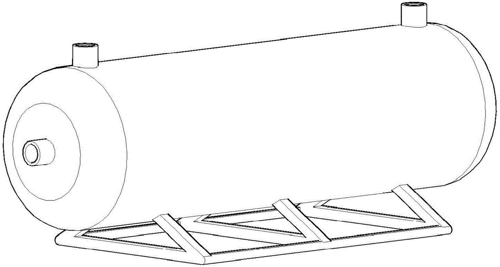
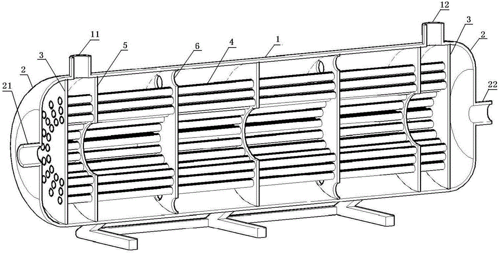
[0027] Such as figure 1 and figure 2 As shown, the shell and tube heat exchanger mainly consists of a shell 1, a tube box 2 located on both sides of the shell 1, a tube plate 3 between the tube box and the shell, and a heat exchange tube 4 placed in the shell composition. A saddle is provided under the casing to fix the shell-and-tube heat exchanger on the ground or other equipment. The housing is generally cylindrical.

[0028] A shell-side fluid inlet 11 is provided on the outer wall of the shell near one end edge of the shell, and a shell-side fluid outlet 12 is provided on the outer wall of the shell near the other end edge of the shell. The interstitial flow exits through the shell-side fluid outlet.

[0029] The tube box at one end of the shell side fluid inlet is provided with a tube side fluid inlet 21, and the other tube box is provided with a tube side fluid outlet 22; On the plate, the openings at both ends of the heat exchange tubes are respectively located i...


PUM


Abstract

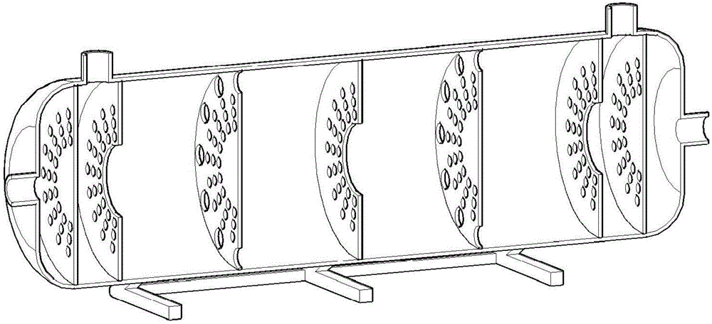
The invention provides a shell-and-tube heat exchanger. The shell-and-tube heat exchanger is mainly composed of a shell, tube boxes located on the two sides of the shell, tube plates located between the tube boxes and the shell, and heat exchange tubes arranged in the shell. A saddle is arranged below the shell and used for fixing the shell-and-tube heat exchanger to the ground or other equipment. The shell is usually cylindrical. Through arched plates and round plates which are arranged alternately, cooling liquid is forced to flow through center holes of the arched plates and then be redirected to flow through the edges of the round plates, the heat exchange tubes are fully cooled, and the phenomenon that the cooling liquid linearly flows to the other end from one end of the shell, and the center position where the heat exchange tubes are concentrated is not sufficiently cooled is avoided.

Description

technical field [0001] The invention relates to a shell-and-tube heat exchanger, which belongs to the optimization technology of the shell-and-tube heat exchanger. Background technique [0002] Shell and tube heat exchangers are widely used in petrochemical, electric power, environmental protection and other industrial fields. A shell-and-tube heat exchanger usually includes a tube box, a tube sheet, a shell, multiple baffles, multiple heat exchange tubes, and the like. Among them, in addition to supporting the heat exchange tubes in the shell of the shell-and-tube heat exchanger, the baffle mainly plays the role of making the fluid flow according to a specific path, increasing the flow rate of the shell-side fluid, increasing the degree of turbulence, and improving the heat transfer characteristics. . [0003] The baffles of the existing shell-and-tube heat exchangers include arcuate baffles and spiral baffles. [0004] Ordinary arcuate baffles are flat plate, that is, t...

Claims


Application Information

Patent Timeline
IPC IPC(8): F28D7/16F28F9/24
CPCF28D7/1607F28D7/1669F28F9/22F28F9/24F28F2009/226F28F2210/10
Inventor 肖晟
Owner ZJMECH TECH
Why Eureka
Eureka Blog
Learn More