Method for detecting insulation device

An insulation device and insulation resistance technology are applied in the field of computer programs and systems for implementing the method to achieve the effect of simple integration

Active Publication Date: 2015-09-30
ROBERT BOSCH GMBH
View PDF9 Cites 4 Cited by
  • Summary
  • Abstract
  • Description
  • Claims
  • Application Information

AI Technical Summary

Problems solved by technology

Such a measurement may take several minutes because the measured current includes different components with decay times of different lengths

Method used


Image

  • Method for detecting insulation device
  • Method for detecting insulation device
  • Method for detecting insulation device

Examples


Embodiment Construction

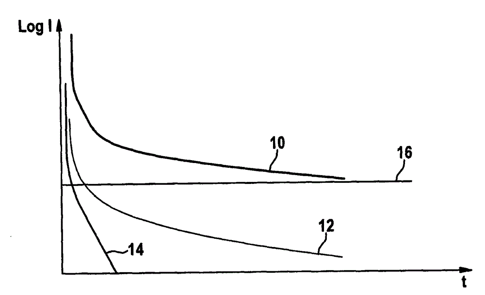
[0032] figure 1 Schematic representation with sink current component I abs Variation process 12. Capacitive current component I kap Variation process 14 and leakage current I leck The total current profile 10 of the profile 16 .

[0033] exist figure 1 The logarithm (Log) of the medium current I is plotted as a function of time t. Here, the total current I is plotted in addition to the total current profile 10 ges Each current component I kap , I abs . Thus the total current I ges including sink current components I abs and capacitive current component I kap The parasitic current component I par . For example, the sink current component I abs and capacitive current component I kap are given by descending exponential functions with initial values ​​and decay times, respectively. In the illustrated embodiment, the capacitive current component I kap The initial value I of the change process 14 kap,0 and decay time 1 / k kap greater than the sink current component ...


PUM


Abstract

The present invention relates to a method for detecting insulation resistance of an insulation device of a battery. The method comprises the steps of applying a measuring voltage to the insulation device, measuring a total current changing process (28, 30) in a set measuring time interval ([delta]t), and comparing the total current changing process (28, 30) measured in the set measuring time interval ([delta]t) with a reference current changing process. In addition, the present invention also relates to a computer program and system for implementing the method.

Description

technical field [0001] The invention relates to a method for testing the insulation resistance of an insulation device of a battery pack. Furthermore, the invention also relates to a computer program and a system for performing this method. Background technique [0002] High voltage components are used in rechargeable battery packs for electric or hybrid vehicles, which must be insulated from other components, such as low voltage components and the environment. Failure of the insulation is a high safety risk and can lead to destruction of the battery pack. The functional capability of the insulation is therefore checked already during the production of the battery and in particular the high-voltage components of the battery in order to detect damaged insulation as early as possible during the production process or during battery operation. [0003] To test the insulation, the insulation resistance is usually measured, which is correspondingly high when the insulation is fu...

Claims


Application Information

Patent Timeline
Patent Type & Authority Applications(China)
IPC IPC(8): G01R27/02G01R31/02
CPCB60L1/08B60L3/0069B60L2240/662B60L2240/667B60L58/21B60L58/26G01R31/3865G01R31/52Y02T10/70Y02T10/72Y02T90/16
Inventor G·加兰布S·本茨
Owner ROBERT BOSCH GMBH
Why Eureka
Try Eureka