
Monitoring system for videos of microwave relay station and application thereof

A technology of video surveillance system and relay station, which is applied in the direction of closed-circuit television system, etc., can solve the problems of undetectable, poor living conditions, high maintenance cost, etc., and achieve good openness and scalability, information storage network, and intelligent maintenance management Effect

Inactive Publication Date: 2015-09-30
STATE GRID CORP OF CHINA +1
View PDF0 Cites 0 Cited by
  • Summary
  • Abstract
  • Description
  • Claims
  • Application Information

AI Technical Summary

Problems solved by technology

Microwave relay stations are generally located on remote and high mountains, with inconvenient transportation and poor living conditions. When the mountains are closed by heavy snow in winter, it is very difficult to transport living materials. Gas poisoning and other diseases are difficult to treat in time, and even cannot be discovered and the treatment is delayed, which poses a great safety risk
[0003] At present, microwave relay stations mostly adopt the way of guarding at home. Most of the left-behind personnel are retired old couples who stay on duty in remote areas or mountains for many years. Their lives are relatively closed and the living environment is poor. Especially in winter, when the mountains are closed by heavy snow, they must solve the necessary water supply and power supply. High maintenance costs such as heating
It is inconvenient to see a doctor when you are sick. Once gas poisoning, injury and other emergencies occur, it is not easy to be found, which will delay the treatment and cause adverse consequences

Method used


Image

  • Monitoring system for videos of microwave relay station and application thereof

Examples


Embodiment Construction

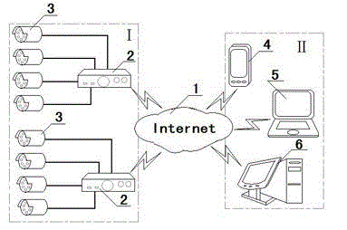
[0024] attached by figure 1 Shown: The system includes:

[0025] A wide area network (public network) 1;

[0026] At least two DVR host devices 2 connected to the wide area network;

[0027] At least four cameras3 connected to each DVR host device;

[0028] A smart phone terminal 4, a laptop computer 5 or a desktop computer 6 connected to the wide area network.

[0029] The DVR host device 2 and the camera 1 are set in the microwave relay station I, and the smart phone terminal 4, laptop computer 5 or desktop computer 6 are set in the monitoring management center II.

[0030] The system equipment utilizes Ethernet, such as: ADSL, optical fiber private network, local area network, etc., through TCP / IP

[0031] Protocol exchange of video and data information, to achieve complete digitization and networking.

[0032] Working principle: The whole system is mainly composed of multiple front-end monitoring points (camera and DVR host equipment) and a monitoring management cente...


PUM


Abstract

The invention relates to a monitoring system, and specifically relates to a monitoring system for the videos of a microwave relay station in an electric power system and an application thereof. The system comprises a wide area network (public network), at least two pieces of DVR mainframe equipment connected with the wide area network, at least four cameras connected with each piece of DVR mainframe equipment, and a smart mobile phone terminal or a notebook computer or a desktop computer connected with the wide area network, wherein the DVR mainframe equipment and the cameras are arranged in the microwave relay station I, and the smart mobile phone terminal or the notebook computer or the desktop computer is arranged in a monitoring and control management centre II. The system disclosed by the invention realizes uploading for a remote video system to a master control centre, and carries out unified management, and video forwarding, monitoring and control on various front-end monitoring points (cameras). The system is a 'digitalized, networked and centralized-management' intelligent network monitoring and control management system, and achieves the objectives of 'system integration, information storage networking and maintenance management intellectualization'.

Description

technical field [0001] The invention relates to a monitoring system, in particular to a video monitoring system of a microwave relay station in a power system and its application. Background technique [0002] The microwave communication of the power system was built in the 1980s. Many microwave stations have operators on duty. With the popularization of optical fiber communication, microwave communication has gradually withdrawn, and the management of microwave stations has changed from manned to manned. Microwave relay stations are generally located on remote and high mountains, with inconvenient transportation and poor living conditions. When the mountains are closed by heavy snow in winter, it is very difficult to transport living materials. Gas poisoning and other diseases are difficult to treat in time, or even cannot be discovered and the treatment is delayed, which poses a great safety risk. [0003] At present, microwave relay stations mostly adopt the way of guard...

Claims


Application Information

Patent Timeline
IPC IPC(8): H04N7/18
Inventor 宋鑫宋丽红王祝民张英杰高洪阁
Owner STATE GRID CORP OF CHINA
Learn More