Pipe straightening machine

A technology for straightening machines and pipe fittings, applied in the field of pipe straightening machines, can solve the problems of affecting the straightening effect, the deformation of the top, the poor matching effect of the top and the groove, etc., and achieve the effect of improving the straightening effect and improving the service life.

Active Publication Date: 2015-10-07
ZHEJIANG HONGDA GRP WENLING DAFENG ELECTRONICS
View PDF6 Cites 9 Cited by
  • Summary
  • Abstract
  • Description
  • Claims
  • Application Information

AI Technical Summary

Problems solved by technology

[0004] (1) Since the raw material mandrel tube is originally in the first state of bending, in this first state, the end of the raw material mandrel tube is also in the bent state, and the matching process between the top and the groove is difficult, even if If it is forced to fit in place, there will be a large gap between the raw material mandrel pipe fitting and the placement bracket, not only the matching effect between the top and the groove is not good, but also directly affect the straightening effect in the later stage;
[0005] (2) After the straightening action of the screw rod, the bent raw material mandrel tube will be straightened, and the end of the raw material mandrel tube will be straightened accordingly, and at this time the top will not be able to match In addition, when the whole raw material mandrel tube is straightened, the transverse length of the raw material mandrel tube will be slightly longer. After long-term use, the top will be squeezed by the groove of the raw material mandrel tube. Deformation or even breakage due to pressure, which seriously affects the normal use process

Method used


Image

  • Pipe straightening machine
  • Pipe straightening machine
  • Pipe straightening machine

Examples


Embodiment Construction

[0027] In order to make the purpose, technical solutions and advantages of the embodiments of the present invention clearer, reference will be made below Figure 1 to Figure 9 The embodiment of a pipe straightening machine of the present invention is further clearly and completely described. Apparently, the described embodiments are some, but not all, embodiments of the present invention. Based on the described embodiments of the present invention, all other embodiments obtained by persons of ordinary skill in the art without creative efforts shall fall within the protection scope of the present invention.

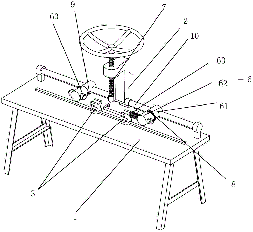
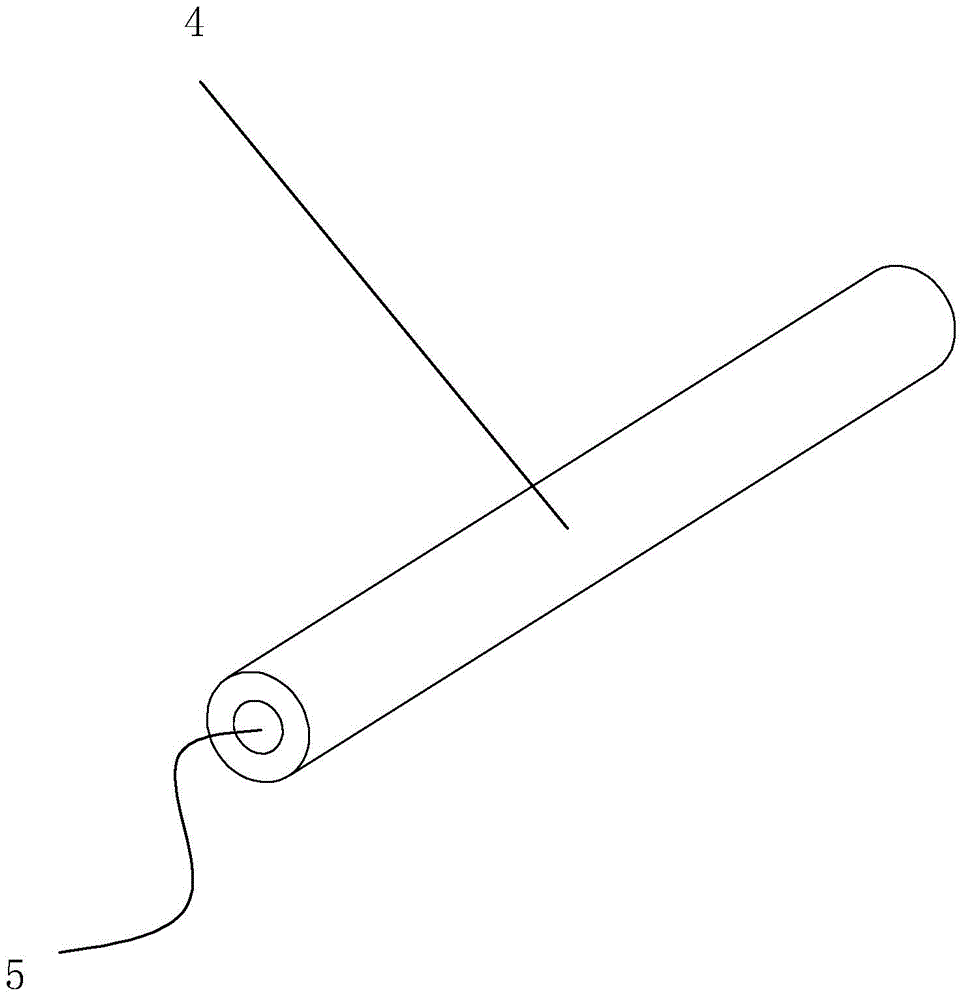
[0028] Such as figure 1As shown, the main structure of this pipe fitting straightening machine includes a placement table 1, on which a straightening machine bracket 2 is fixed, a placement bracket 3 for placing the raw material mandrel pipe fittings 4 to be straightened, and a The abutment mechanism 6 that abuts against the groove 5 at the end of the raw material mandre...


PUM


Abstract

The invention discloses a pipe straightening machine, and aims to provide a pipe straightening machine which can improve the straightening effect and prolong the service life of an abutting piece. According to the technical scheme, the pipe straightening machine is characterized by comprising a placement table; a straightening machine support, placement supports where a raw material central spindle pipe to be straightened is placed and abutting mechanisms used for abutting against grooves in the ends of the raw material central spindle pipe are fixedly arranged on the placement table; an abutting part capable of abutting against the raw material central spindle pipe placed on the placement supports is arranged on the straightening machine support; each abutting mechanism comprises an abutting base and an abutting head; the abutting bases are transversely connected with the placement supports in a sliding mode, and the abutting heads are connected with the abutting bases in a rotating mode; second limiting parts are arranged on the abutting bases and used for limiting sliding motion of the abutting bases, and tips are arranged on the abutting heads; driving pieces used for driving the abutting heads to rotate and first limiting parts used for limiting rotation of the abutting heads are arranged on the abutting bases. When the first limiting parts are in a limiting state, the length direction of the tips is parallel with the horizontal direction.

Description

technical field [0001] The invention relates to a straightening machine for pipe fittings, more specifically, it relates to a straightening machine for pipe fittings which can improve the straightening effect and the service life of the abutting parts. Background technique [0002] In the motor manufacturing industry, the raw material mandrel pipe fittings are usually used to make the motor rotor shaft core, and the concentricity of the motor rotor shaft core will directly determine the actual use effect and service life of the motor. The concentricity requirements are relatively high, but affected by practical factors, including the transportation process and the processing process, the raw material mandrel pipe fittings will be affected by many factors, resulting in low concentricity and even bending. [0003] In order to reuse the bent and deformed raw material mandrel pipe fittings and reduce the manufacturing cost of manufacturing enterprises, a straightening machine fo...

Claims


Application Information

Patent Timeline
Patent Type & Authority Applications(China)
IPC IPC(8): B21D3/10
CPCB21D3/10
Inventor 赵如友
Owner ZHEJIANG HONGDA GRP WENLING DAFENG ELECTRONICS
Why Eureka
Try Eureka