
Snap spring automatic press fitting mechanism on clutch driving disk

A technology for driving discs and clutches, applied in metal processing, metal processing equipment, manufacturing tools, etc., can solve the problems of low assembly efficiency, insufficient flexibility, and inability to guarantee assembly quality, so as to improve production efficiency and automation, and reduce labor. the effect of strength

Active Publication Date: 2015-10-07
ANHUI JEE AUTOMATION EQUIP CO LTD
View PDF6 Cites 20 Cited by
  • Summary
  • Abstract
  • Description
  • Claims
  • Application Information

AI Technical Summary

Problems solved by technology

[0002] Most of the existing circlip press fittings are manually assembled or assembled with auxiliary tooling. Manually assembling circlips can only be used for small circlips. When assembling large circlips, auxiliary tooling is used and the assembly space is limited. Different specifications Tooling is replaced on different occasions, and the flexibility is insufficient, which can easily cause damage to the circlip. Generally speaking, the assembly efficiency of the current assembly method is low, and the assembly quality cannot be guaranteed. big uncertainty

Method used


Image

  • Snap spring automatic press fitting mechanism on clutch driving disk
  • Snap spring automatic press fitting mechanism on clutch driving disk
  • Snap spring automatic press fitting mechanism on clutch driving disk

Examples


Embodiment Construction

[0019] The present invention will be further described below in conjunction with accompanying drawing:

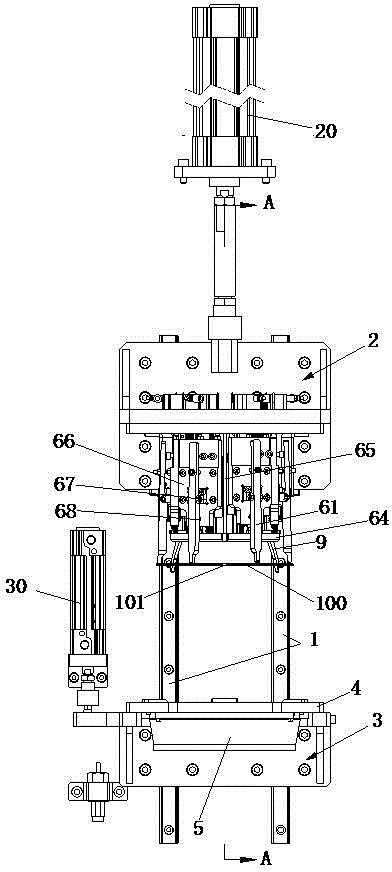
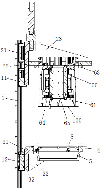
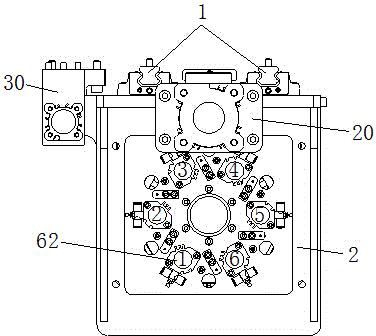
[0020] Such as figure 1 , figure 2 , image 3 , Figure 4 The shown automatic clamp spring pressing mechanism on the clutch drive disc includes a slide rail 1 fixed on the clamp spring press machine and arranged in a vertical direction. The slide rail 1 is provided with upper, lower Slide table 2,3, upper and lower table 2,3 are respectively driven by upper and lower cylinders 20,30 to move along the direction defined by slide rail 1, slide table 3 is provided with support plate 4 for placing jumper 100, supports The bottom of the plate 4 is connected with a guide cone barrel 5, the diameter of the upper opening of the guide cone barrel 5 is large, and the diameter of the lower opening is small, and the inner diameter of the lower opening of the guide cone barrel 5 coincides with the diameter of the entrance of the clutch drive disc circlip groove. A press-fit assembly...


PUM


Abstract

The invention relates to a snap spring automatic press fitting mechanism on a clutch driving disk. The mechanism comprises slide rails provided with an upper sliding table and a lower sliding table, a supporting plate used for containing a snap spring is arranged on the lower sliding table, the lower portion of the supporting plate is connected with a guiding conical barrel, the inner diameter of a lower opening of the guiding conical barrel is matched with the diameter of a snap spring groove inlet of the clutch driving disk, the upper sliding table is provided with a press fitting assembly used for pressing the snap spring to the clutch driving disk, the press fitting assembly comprises press fitting fingers and cylinders driving the press fitting fingers to move, and the press fitting fingers move downwards under the action of the cylinders so that the snap spring placed on the supporting plate can be pressed into a snap spring groove of the clutch driving disk along the inner wall of the guiding conical barrel. Due to the technical scheme, the lower sliding table is pre-pressed to the clutch driving disk through a lower cylinder, then the upper sliding table is driven to an assigned position through an upper cylinder, the six press fitting fingers are drive to sequentially move downwards through the cylinders, the action of manually installing the snap spring is simulated, and the snap spring is pressed in place in sequence.

Description

technical field [0001] The invention relates to an automatic press-fitting mechanism for a clip spring on a clutch driving disc. Background technique [0002] Most of the existing circlip press fittings are manually assembled or assembled with auxiliary tooling. Manually assembling circlips can only be used for small circlips. When assembling large circlips, auxiliary tooling is used and the assembly space is limited. Different specifications Tooling is replaced on different occasions, and the flexibility is insufficient, which can easily cause damage to the circlip. Generally speaking, the assembly efficiency of the current assembly method is low, and the assembly quality cannot be guaranteed. big uncertainty. Contents of the invention [0003] The object of the present invention is to provide an automatic pressing mechanism for the jumper on the clutch drive disc, [0004] In order to achieve the above object, the present invention adopts the following technical so...

Claims


Application Information

Patent Timeline
Patent Type & Authority Applications(China)
IPC IPC(8): B23P19/027
CPCB23P19/027
Inventor 刘蕾王剑波汪波
Owner ANHUI JEE AUTOMATION EQUIP CO LTD
Learn More