Grinding workbench

A workbench and platform technology, applied in the field of machining, can solve the problems of resource waste, large space occupation, and oil leakage of the hydraulic system, and achieve the effect of balancing grinding force, improving work efficiency, and simple and light structure

Active Publication Date: 2015-10-07
旌德县小春机械厂
View PDF8 Cites 2 Cited by
  • Summary
  • Abstract
  • Description
  • Claims
  • Application Information

AI Technical Summary

Problems solved by technology

The lifting mechanism in the existing grinding machine is mostly a hydraulic mechanism to control the lifting of the grinding table. The grinding table is heavy and complex in structure, and the response of the lifting control is slow. In addition, the hydraulic system is prone to oil leakage during work, resu

Method used


Image

  • Grinding workbench
  • Grinding workbench

Examples


Embodiment Construction

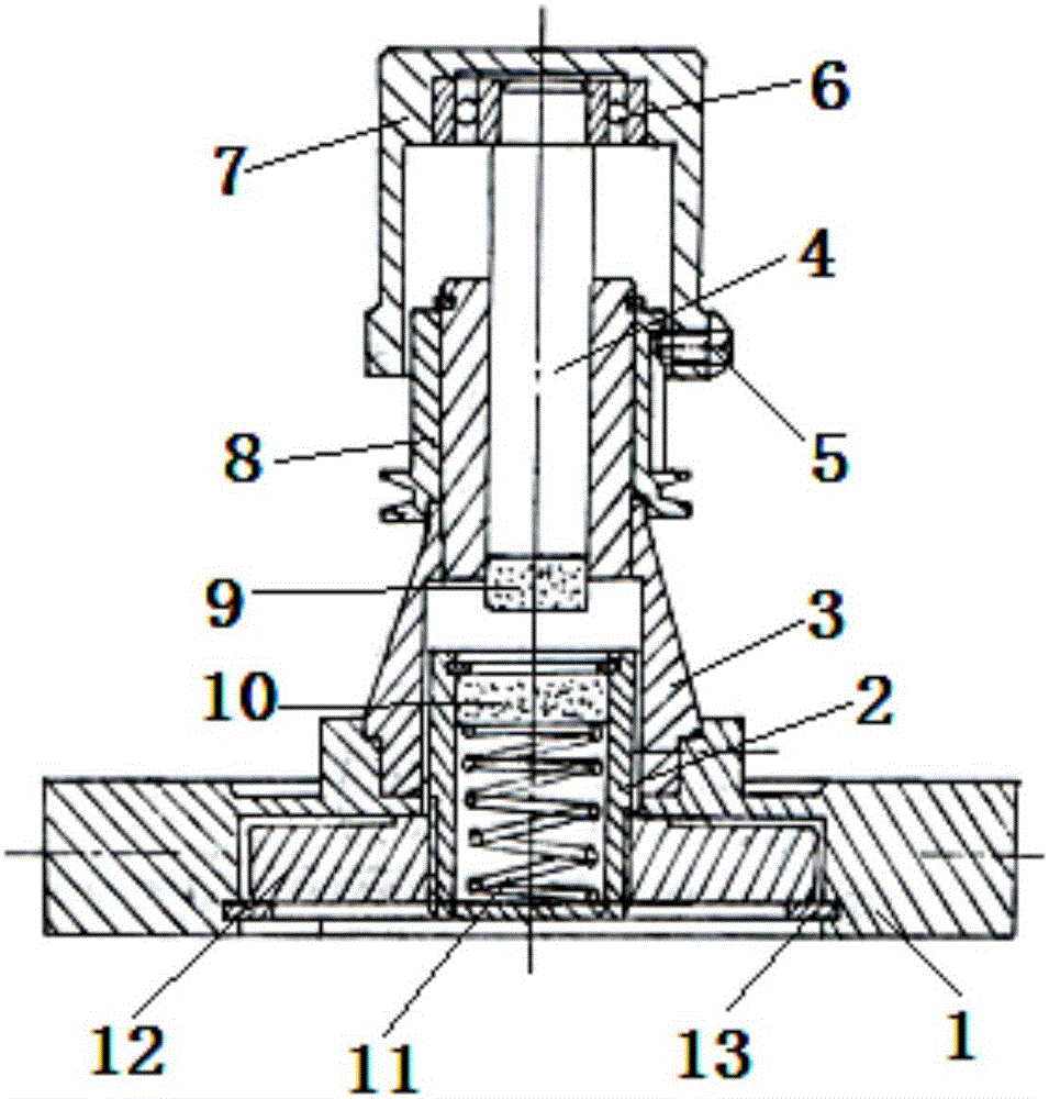
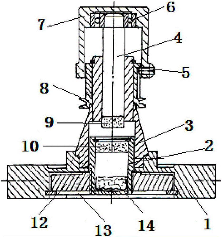
[0019] The specific implementation manner of the present invention will be described in further detail below by describing the embodiments with reference to the accompanying drawings.

[0020] The grinding workbench of the present invention, as figure 1 , 2 As shown, it includes the base 1, the ejector rod 4 and the platform seat 7 arranged on the upper end of the ejector rod 4, wherein the base 1 can make the workbench stable to use. Grinding operation. The grinding table is equipped with a floating lifting device to balance the force during the grinding process, ensure uniform and stable grinding, and improve the processing quality of the wire drawing die.

[0021] The lifting device in the present invention is a magnetic lifting device, and a first magnetic block 9 is provided at the lower end of the push rod 4 , and a second magnetic block 10 opposite to the first magnetic block 9 is provided below the first magnetic block 9 . When the wire drawing die is placed on the ...


PUM


Abstract

The invention discloses a grinding workbench. The grinding workbench comprises a base (1), a push rod (4) and a platform seat (7) arranged at the upper end of the push rod (4). The lower end of the push rod (4) is provided with a first magnetic patch (9). A second magnetic patch (10) is arranged below the first magnetic patch (9) and has magnetism opposite to the first magnetic patch. A secondary support part used for providing a thrust supporting effect is arranged below the second magnetic patch (10).The grinding workbench has following beneficial effects: due to a simple structure and low weight, the grinding workbench is adapted to a wire-drawing die in the larger size range for grinding and polishing so that border applicability is obtained and convenience is achieved so that working efficiency is improved and working cost is reduced.

Description

technical field [0001] The invention belongs to the technical field of machining, and more specifically relates to a grinding workbench for grinding and polishing wire drawing dies. Background technique [0002] Grinding is a high-precision machining machine. During the process of grinding and polishing the center hole of the wire drawing die, the worktable is a liftable structure to ensure uniform force. The lifting mechanism in the existing grinding machine is mostly a hydraulic mechanism to control the lifting of the grinding table. The grinding table is heavy and complex in structure, and the response of the lifting control is slow. In addition, the hydraulic system is prone to oil leakage during work, resulting in waste of resources and pollution of the processing environment. . There are also some control worktables that are pulled up by gravity. This kind of external structure is complicated, takes up a lot of space, and it is not convenient to adjust the control pre...

Claims


Application Information

Patent Timeline
IPC IPC(8): B24B37/34
CPCB24B37/34
Inventor 沈小春
Owner 旌德县小春机械厂
Why Eureka
Try Eureka