Pipe fitting operation robot
A technology for working robots and pipe fittings, used in manipulators, program-controlled manipulators, chucks, etc., can solve problems such as high cost and complex movement, and achieve the effects of simple control, simple planning and compact structure
- Summary
- Abstract
- Description
- Claims
- Application Information
AI Technical Summary
Problems solved by technology
Method used
Image


Examples
Embodiment 1
[0038] Such as figure 2 As shown, the telescopic mechanism includes an upper guide rail 401, a lower guide rail 402, an upper slider 403, a lower slider 404, a working head base 405, a nut 406, a screw 407 and a screw power mechanism 408; The upper guide rail 401 and the lower guide rail 402 are installed on the telescopic arm base 304, the upper slider 403 and the lower slider 404 slide along the upper guide rail 401 and the lower guide rail 402 respectively, and the The working head base 405 is fixedly installed on the upper slider 403 and the lower slider 404 at the same time, and the nut 406 is fixedly installed on the working head base 405 and threadedly matched with the screw rod 407. The rod power mechanism 408 is installed on the telescopic arm base 304 and drives the screw rod 407 to rotate, and the working arm 5 is installed on the working head base 405 .
[0039] In this embodiment, the screw power mechanism 408 provides power to drive the screw 407 to rotate. Aft...
Embodiment 2
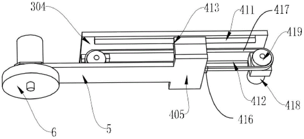
[0042] Such as image 3 As shown, the telescopic mechanism includes an upper rail 411, a lower rail 412, an upper slider 413, a lower slider 414, a working head base 405, a connecting block 416, a telescopic belt 417, a telescopic belt power mechanism 418 and Telescopic pulley 419; the upper side track 411 and the lower side track 412 are installed on the telescopic arm base 304, and the upper side slider 413 and the lower side slider 414 slide on the upper side track 411 and the lower side respectively Track 412, the working head base 405 is installed on the upper slider 413 and the lower slider 414 at the same time, the working head base 405 is fixedly connected with the telescopic belt 417 through the connecting block 416, so The telescopic belt 417 is sleeved on the telescopic pulley 419 and driven by the telescopic belt power mechanism 418 to drive the working head base 405 .
[0043] The working head base 405 is fixedly connected with the telescopic belt 417 through the...
Embodiment 3
[0045] Such as Figure 4 As shown, the telescopic mechanism includes an upper rail 411, a lower rail 412, an upper slider 413, a lower slider 414, a working head base 405, a telescopic rack 426, a telescopic gear 427 and a telescopic gear power mechanism 428 The upper rail 411 and the lower rail 412 are mounted on the telescopic arm base 304, the upper slider 413 and the lower slider 414 slide on the upper rail 411 and the lower rail 412 respectively, The working head base 405 is installed on the upper slider 413 and the lower slider 414 at the same time, the telescopic gear 427 and the telescopic gear power mechanism 428 are installed on the telescopic arm base 304, and the telescopic rack 426 is fixedly installed on the working head base 405 , and the telescopic gear 427 meshes with the telescopic rack 426 .
[0046] In this embodiment, the transmission mode for the telescoping of the working arm 5 is rack and pinion transmission, and the transmission is precise. Wherein, ...
PUM
 Abstract
Description
Claims
Application Information
 - R&D
- Intellectual Property
- Life Sciences
- Materials
- Tech Scout
- Unparalleled Data Quality
- Higher Quality Content
- 60% Fewer Hallucinations
Browse by: Latest US Patents, China's latest patents, Technical Efficacy Thesaurus, Application Domain, Technology Topic, Popular Technical Reports.
© 2025 PatSnap. All rights reserved.Legal|Privacy policy|Modern Slavery Act Transparency Statement|Sitemap|About US| Contact US: help@patsnap.com