Conveying structure of chain type engine assembly line

A transmission structure and engine technology, applied in conveyors, transportation and packaging, etc., can solve the problems of low effective utilization of equipment, inability to assemble underground return sections, and large production workshops, saving length and space, improving equipment utilization, and improving The effect of production efficiency

Inactive Publication Date: 2015-10-07
GUANGXI YUCHAI MASCH CO LTD
View PDF7 Cites 0 Cited by
  • Summary
  • Abstract
  • Description
  • Claims
  • Application Information

AI Technical Summary

Problems solved by technology

[0003] The engine (automobile) assembly line of the above-mentioned upper and lower return roller table type, rectangular roller table type, fixed assembly island type, and mobile assembly trolley type cannot be flat with the ground because the assembly tray (bracket) cannot be flat with the ground, and the operator and the assembled parts are placed at the bottom of the assembly line. On both sides, when the engine (vehicle) is running, the operator and assembly parts cannot follow the movement, and they need to wait for the engine (vehicle) to stop running before assembling, which affects the production efficiency
Although the operators and assembly parts of the crawler assembly line can flow simultaneously with the circulation of the engine (car), without affecting the production efficiency, but because the crawler assembly line can only be designed as a straight line, the assembly pallet (bracket) is returned through the underground, The underground return section cannot be assembled, the effective utilization of equipment is low, and the production workshop occupied is large

Method used


Image

  • Conveying structure of chain type engine assembly line
  • Conveying structure of chain type engine assembly line
  • Conveying structure of chain type engine assembly line

Examples


Embodiment Construction

[0021] The specific embodiments of the present invention will be described in detail below with reference to the drawings, but it should be understood that the protection scope of the present invention is not limited by the specific embodiments.

[0022] Unless otherwise expressly stated otherwise, throughout the specification and claims, the term "comprising" or its transformations such as "including" or "including" will be understood to include the stated elements or components, and not Other elements or other components are not excluded.

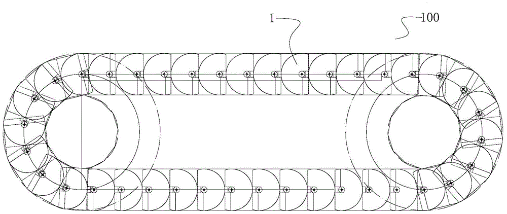
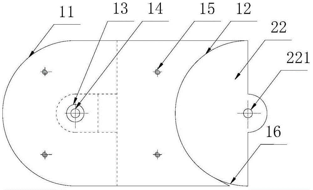
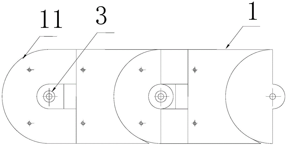
[0023] Such as Figure 1 to Figure 3 As shown, a transmission structure 100 for a chain-type engine assembly line according to a specific embodiment of the present invention includes a plurality of unit plates 1 and a plurality of connecting parts (not marked in the figure). One end of each unit plate 1 is a circular convex block 11, and the other end of each unit plate 1 is a circular concave block 12. A number of connecting parts are corre...


PUM


Abstract

The invention discloses a conveying structure of a chain type engine assembly line. The conveying structure comprises a plurality of unit plates and a plurality of connecting parts. A round convex block is arranged at one end of each unit plate, and round concave blocks are arranged at the other ends of the unit plates. The connecting parts are correspondingly arranged on the lower sides of the unit plates respectively and comprise front end connecting blocks on the lower sides of the round convex blocks and rear end connecting blocks, and the rear end connecting blocks extend outwards from the lower sides of the round concave blocks. The adjacent unit plates are connected together through hinge joint of the front end connecting blocks and the rear end connecting blocks, and then the unit plates are combined to form a moving annular face. According to the conveying structure of the chain type engine assembly line, the equipment utilization rate of the assembly line can be effectively improved, and production efficiency can be improved.

Description

Technical field [0001] The invention relates to the field of vehicle assembly, in particular to a transmission structure of a chain-type engine assembly line. Background technique [0002] At present, the design structure of the engine (automobile) assembly line includes the upper and lower return roller table type, the rectangular roller table type, the crawler type, the fixed assembly island type, and the mobile assembly trolley type. The upper and lower return roller conveyors are used in production workshops subject to space constraints. The lower roller conveyors can be assembled and the upper overhead roller conveyors return to the pallet structure. The rectangular roller table adopts two parallel roller table assembly, the two ends of the roller table adopt corner table and roller table or use RGV mobile trolley to transplant and assemble pallets. The crawler-type assembly line is installed on the foundation by digging a pit. The upper surface of the crawler is connected ...

Claims


Application Information

Patent Timeline
Patent Type & Authority Applications(China)
IPC IPC(8): B65G17/06
CPCB65G17/065
Inventor 谭伟权周建刘伟琨卢建律朱茂保黎雪清
Owner GUANGXI YUCHAI MASCH CO LTD
Why Eureka
Try Eureka