
Solid-liquid two-phase energy dissipating fender and manufacturing method thereof

A cancellation and fender technology, applied in shipping equipment, climate change adaptation and other directions, can solve the problems of secondary injury to ships or personnel, and can not be reused, and achieve the effect of good buffering energy absorption and low cost.

Active Publication Date: 2015-10-07
江苏宏远科技工程有限公司 +1
View PDF5 Cites 2 Cited by
  • Summary
  • Abstract
  • Description
  • Claims
  • Application Information

AI Technical Summary

Problems solved by technology

However, this kind of energy-dissipating fender cannot be used again after being hit, and these rigid fenders may also cause secondary damage to ships or personnel due to collision, fragmentation and flying strikes.

Method used


Image

  • Solid-liquid two-phase energy dissipating fender and manufacturing method thereof
  • Solid-liquid two-phase energy dissipating fender and manufacturing method thereof
  • Solid-liquid two-phase energy dissipating fender and manufacturing method thereof

Examples


Embodiment 1

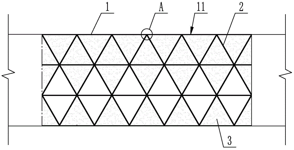
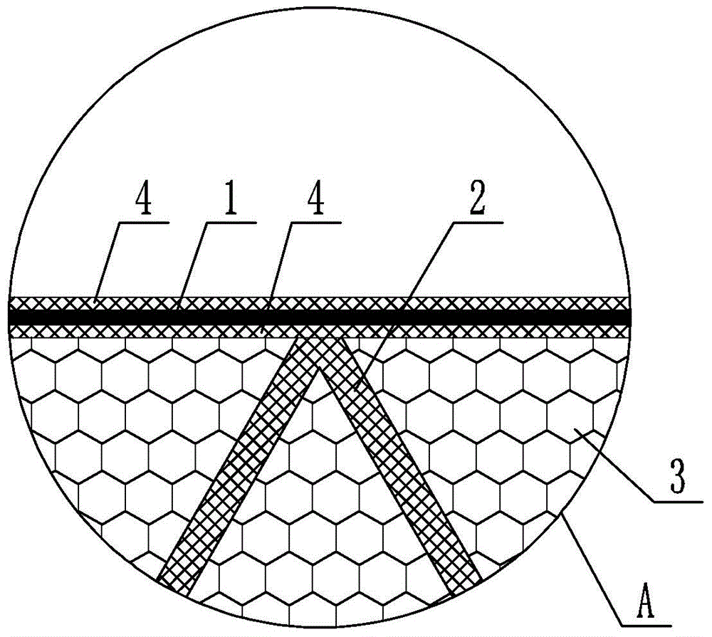
[0032] A solid-liquid two-phase energy-dissipating fender includes an outer shell 1 and a hollow tube 2 arranged inside the outer shell 1. The material of the outer shell 1 can be steel, composite material, or steel-clad composite material or composite material-clad steel. In this example, if figure 2 As shown, the shell 1 is a steel plate, and the inner and outer surfaces of the steel plate are provided with an anti-corrosion layer 4 .

[0033] The shell 1 has a collision surface 11, and the hollow tubes 2 are integrally formed with the shell 1, and two adjacent hollow tubes 2 are in surface contact and tightly fitted, and the hollow tubes 2 are arranged and combined to fill the entire inner space of the shell 1. The shape of the hollow tube 2 is a prism, such as a triangular prism or a quadrangular prism. The cross-sections of the prisms are respectively triangular or square. Two adjacent hollow tubes 2 are in surface contact with each other on the sides of the prism. The ...

Embodiment 2

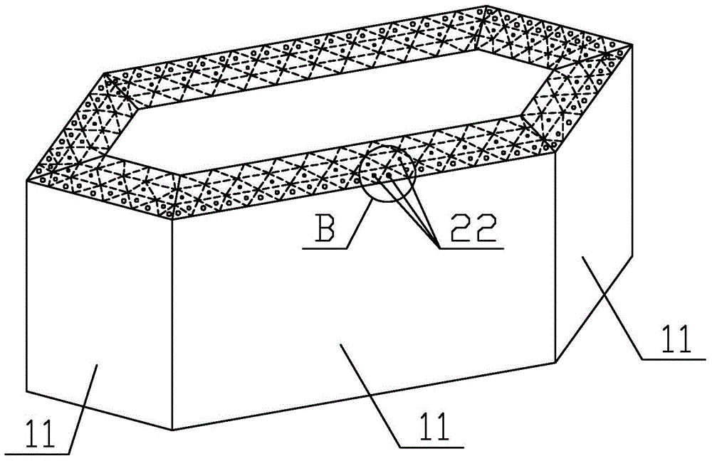
[0040] This embodiment is roughly the same as Embodiment 1, the difference is that, as Figure 5 As shown, the injection of the hollow tube 2 filled with the liquid 3 is realized in that the hollow tube 2 is a closed structure, and the hollow tube 2 filled with the liquid 3 has a prestressed hole 22 that can be broken after being hit, and the prestressed hole 22 and The remaining parts of the hollow tube 2 jointly form a hollow structure for filling the liquid 3 . The prestressed hole 22 is a closed structure before being hit by an external force, and the hole will be broken after being hit. In this embodiment, the thickness of the prestressed hole 22 is smaller than that of its surroundings. The thickness of the prestressed hole 22 is related to the impact force, and it can be designed that when a certain impact force is reached, the prestressed hole 22 will be broken. After the prestressing hole 22 is broken, the liquid 3 in the hollow tube 2 will be sprayed out to achieve...

Embodiment 3

[0043] This embodiment is roughly the same as Embodiment 1, the difference is that, as Figure 7 As shown, the diameter of the hollow tube 2 filled with the liquid 3 gradually decreases from the collision surface 11 inward as the collision depth increases.


PUM

PropertyMeasurementUnit
Pressure resistanceaaaaaaaaaa

Abstract

The invention relates to a solid-liquid two-phase energy dissipating fender and a manufacturing method thereof. The solid-liquid two-phase energy dissipating fender comprises a shell and hollow pipes arranged in the shell. The shell is provided with an impact bearing face. The hollow pipes and the shell are integrally formed. Every two adjacent hollow pipes are in face contact. A part of the hollow pipes are hollow, and the other hollow pipes are filled with liquid. The manufacturing method of the solid-liquid two-phase energy dissipating fender comprises the steps that formed pipes are used as pipe molds for manufacturing the hollow pipes; the pipe molds are covered with fiber cloth; then, a VIP technology is adopted, the pipe molds and the fiber cloth form the hollow pipes in an integrated mode, and the hollow pipes and a shell mold are integrally formed. The hollow pipes and the shell are of an integrated structure, a part of the hollow pipes are filled with liquid, and cost is low; during an impact, the liquid can be sprayed by through holes or prestress holes to dissipate energy, energy conversion can be achieved, and the buffering effect and the energy absorbing effect are good; every two adjacent hollow pipes are independent of each other, after a part of the hollow pipes are cracked due to an impact, the remaining hollow pipes can still be used repeatedly.

Description

technical field [0001] The invention relates to an energy dissipation fender, in particular to a solid-liquid two-phase energy dissipation fender and a preparation method thereof. Background technique [0002] Energy dissipation fenders are mainly used for the protection of bridge piers, so that the impact damage of the hull on the bridge piers is minimized, and it also plays a certain role in protecting the hull. However, the existing energy-dissipating fenders generally use steel boxes to cover the outside of the pier, so that when the hull hits the pier, the impact time is prolonged and the loss is reduced. However, such energy-dissipating fenders generally cannot be used again after being hit, and these rigid fenders may also cause secondary damage to ships or personnel due to collision, fragmentation and flying strikes. Contents of the invention [0003] The technical problem to be solved by the present invention is: in order to improve the buffering and energy-absor...

Claims


Application Information

Patent Timeline
IPC IPC(8): E02B3/26
CPCY02A30/30
Inventor 蒋超
Owner 江苏宏远科技工程有限公司
Learn More