A hydraulic automatic silting device for an inverted siphon in a pressurized water delivery pipeline

A water pipeline and hydraulic automatic technology, which is applied in water supply installations, water supply main pipelines, and sewer cleaning pipelines, etc., to achieve the effect of small impact on project operation, water saving and good effect.

Active Publication Date: 2016-09-14
浙江省水利水电勘测设计院有限责任公司
View PDF8 Cites 0 Cited by
  • Summary
  • Abstract
  • Description
  • Claims
  • Application Information

AI Technical Summary

Problems solved by technology

[0007] The purpose of the present invention is to overcome the deficiencies of the prior art, and to provide a hydraulic automatic silting device for an inverted siphon pipe in a pressurized water delivery pipeline, which utilizes the pressure of the pressurized pipeline without the need for tunnel emptying, manual dredging or power dredging. The water head discharges the silt at the bottom of the inverted siphon pipe to realize the hydraulic automatic silting of the inverted siphon of the pressurized water delivery pipeline. It has the characteristics of safety and energy saving, good scouring effect, small operation impact, and convenient construction

Method used


Image

  • A hydraulic automatic silting device for an inverted siphon in a pressurized water delivery pipeline
  • A hydraulic automatic silting device for an inverted siphon in a pressurized water delivery pipeline

Examples


Embodiment Construction

[0023] The present invention will be described in further detail below in conjunction with the accompanying drawings.

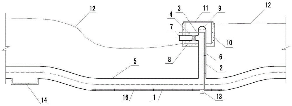
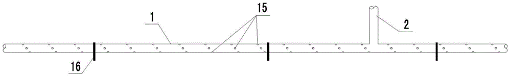
[0024] Such as figure 1 and figure 2 As shown, the present invention has a pressure water pipeline inverted siphon hydraulic automatic silting device, including a horizontal silt suction pipe 1 for sucking silt, a vertical mud pipe 2 for mud transportation and a surface mud discharge for mud discharge Pipe 3; the horizontal silt suction pipe 1 is located at the bottom of the inverted siphon pipe 5 of the water delivery pipeline, and is made of stainless steel steel pipes. Connected to the inner wall of the inverted siphon pipe 5, the fixing part 16 is an Ω-shaped stainless steel gasket, and after fixing the horizontal silt suction pipe 1, it is welded on the bottom inner wall of the inverted siphon pipe 5, and the total area of ​​the orifices of all the silt suction holes 15 is smaller than that of the horizontal silt suction pipe The cross-sectional area ...


PUM


Abstract

The invention discloses waterpower automatic silt-washing device of an inverted siphon in a pressure water delivery pipe. The waterpower automatic silt-washing device comprises a horizontal silt-absorbing tube, a vertical mud-delivering tube and a ground surface mud-discharging tube. The horizontal silt-absorbing tube is arranged at the bottom of the inverted siphon in the pressure water delivery pipe, the two ends of the horizontal silt-absorbing tube are closed, silt-absorbing holes are formed in the periphery of the tube wall, and the total area of the openings of the silt-absorbing holes is smaller than the area of the cross section of the horizontal silt-absorbing tube. The vertical mud-delivering tube is arranged in a water-discharging silo of a pressure water delivery pipeline, the bottom end of the vertical mud-delivering tube is communicated with the horizontal silt-absorbing tube, the top end of the vertical mud-delivering tube is communicated with the ground surface mud-discharging tube, and the height of the vertical ground surface mud-discharging tube is smaller than that of a pressure water head in the inverted siphon. The ground surface mud-discharging tube is located on the ground surface, one end of the ground surface mud-discharging tube is communicated with the vertical mud-discharging tube, the other end of the ground surface mud-discharging tube is starched into a ground surface mud-discharging site, and a mud-discharging valve is arranged on the ground surface mud-discharging tube and is capable of controlling silt discharging. According to the waterpower automatic silt-washing device of the inverted siphon in the pressure water delivery pipe, waterpower automatic silt washing device on the inverted siphon in the pressure water delivery pipe can be achieved under the condition that tunnel emptying, labor decontamination or power decontamination are not needed, and the advantages of being safe, energy-saving, good in silt-washing effect, small in operation influence and convenient to construct are achieved.

Description

technical field [0001] The invention relates to a pipeline desilting device in a water conveyance project, in particular to a hydraulic automatic desilting device for an inverted siphon tube of a pressurized water conveyance pipeline. Background technique [0002] For pressurized water delivery projects, especially long-distance pressurized water delivery projects, inverted siphon structures are often used in areas across river valleys to reduce the impact on ground engineering. pipeline capacity. Aiming at the silt in the pressurized water pipeline, there is no good technical and engineering solution at present. Often, the method of dredging the municipal engineering pipeline is used for reference, and the method of manual dredging is used. During the pipeline maintenance period, dredging personnel and equipment are arranged to enter the pipeline for removal. Accumulation of sediment. Due to the long time for drainage, ventilation, dredging and water filling required for ...

Claims


Application Information

Patent Timeline
Patent Type & Authority Patents(China)
IPC IPC(8): E03B7/09E03F5/20E03F9/00
Inventor 唐巨山张永进赖勇叶洁慧陈知渊王鑫
Owner 浙江省水利水电勘测设计院有限责任公司
Why Eureka
Try Eureka