Device for transferring heat in solid energy storage body by means of high-temperature steam

A high-temperature steam and heat storage device technology, applied in the field of electric energy control, can solve the problems of low heat storage and slow heat transfer speed, and achieve the effects of increasing heat storage, solving slow heat transfer speed, and increasing heat storage temperature

Active Publication Date: 2015-10-07
大连展鹏节能科技开发有限公司
View PDF7 Cites 2 Cited by
  • Summary
  • Abstract
  • Description
  • Claims
  • Application Information

AI Technical Summary

Problems solved by technology

[0004] The present invention solves the problems of low heat storage and slow heat transfer speed when air is used as the heat transfer medium in the prior art, and thus discloses a method for transferring solid storage by high-temperature steam. The device that can generate heat in the body, the specific plan is: including a pure water tank filled with liquid water, a high-temperature steam generator that heats the liquid water into high-temperature steam, a heat storage device, and a saturated steam generator. The high-temperature steam generator is located at The top of the heat storage device is connected to the heat storage device, the pure water tank is connected to the high-temperature steam generator, the high-temperature steam generator is connected to the saturated steam generator, and the water inlet of the saturated steam generator is connected to the pure water The tanks are connected; the high-temperature steam generator includes a high-temperature steam chamber;

Method used


Image

  • Device for transferring heat in solid energy storage body by means of high-temperature steam
  • Device for transferring heat in solid energy storage body by means of high-temperature steam
  • Device for transferring heat in solid energy storage body by means of high-temperature steam

Examples


Embodiment

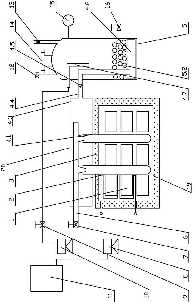
[0031] Embodiment: Turn on the power during the off-peak time, the current flows through the heating wire 2, and the heating wire 2 releases heat to heat the solid heat storage material 1 to 100----1000°C to complete the heat storage process. When the pure water tank 11 is full of pure water, turn on the supplementary water pump 10 and the controller 9, inject pure water into the saturated steam generator 5, control the liquid level to be higher than the filler 5.2, and lower than the height of the saturated steam generator 5. one-third. Then the high-temperature steam water feed pump 8 is turned on, and the water flow is regulated by the flow regulating valve 7. The water flows through the high-temperature steam water pipe 6 and enters the heating pipe 4.1 inside the high-temperature steam generator 20 . Since the high-temperature solid heat storage material 1 conducts heat to the heating tube 4.1 by means of heat radiation and heat conduction, and the temperature of the heat...


PUM


Abstract

The invention discloses a device for transferring heat in a solid energy storage body by means of high-temperature steam, water in a pure water tank is poured into the interior of a heating pipe in a high-temperature steam generator, heat exchange is conducted in a high-temperature state, the liquid water is changed into the high-temperature steam through the heat exchange, the high-temperature steam enters a high-temperature chamber and then enters a saturated steam generator, and the high-temperature steam and the liquid water in the saturated steam generator are fully mixed, and the liquid water is heated to a needed temperature. When the temperature is higher than 100 DEG C, saturated steam with different pressure is generated. According to the device for transferring the heat in the solid energy storage body by means of the high-temperature steam, the characteristics of large latency for vapouring water and good steam flowability are fully utilized, even though vaporization is conducted on the water inside a heat storage body, internal heat of the heat storage body is changed into the latent heat of the steam, the steam is led out, and hot water is added. Accordingly, the problem that the heat transfer speed is slow is solved, the heat storage temperature of the heat storage body can be greatly improved to about 1000 DEG C, and the unit volume heat storage capacity is increased.

Description

technical field [0001] The invention relates to the field of electric energy control, in particular to a device for transferring heat in a solid energy storage body by using high-temperature steam. Background technique [0002] Power is divided into peak power, flat power and valley power according to the time of use. In order to balance the grid, shift peaks to fill valleys, and encourage the use of valley electricity, the price of valley electricity is much lower than normal electricity prices. At present, the technology of using solid heat storage to store and use off-peak electricity is very mature. The process of this technology is to heat the solid heat storage material such as refractory bricks with the heat released by the heating wire, and the heating temperature reaches 400-500°C, and store the heat in the solid heat storage material. When using heat, a fan is used to send air into the channel between the solid heat storage materials. After the air is heated, it ...

Claims


Application Information

Patent Timeline
Patent Type & Authority Applications(China)
IPC IPC(8): F22B1/02F28C3/06
Inventor 邹恩义李静静连志荣李海山
Owner 大连展鹏节能科技开发有限公司
Why Eureka
Try Eureka