Automobile lamp LED light detection mechanism based on photosensitive sensors
A technology of photosensitive sensor and detection mechanism, which can be used in lamp testing, instruments, measuring electricity and other directions, and can solve problems such as detection
- Summary
- Abstract
- Description
- Claims
- Application Information
AI Technical Summary
Problems solved by technology
Method used
Image

Examples
Embodiment Construction
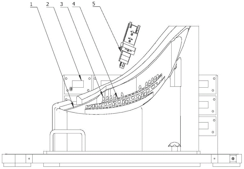
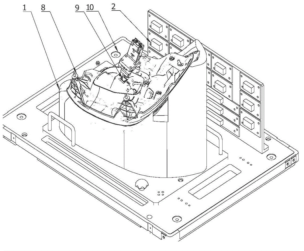
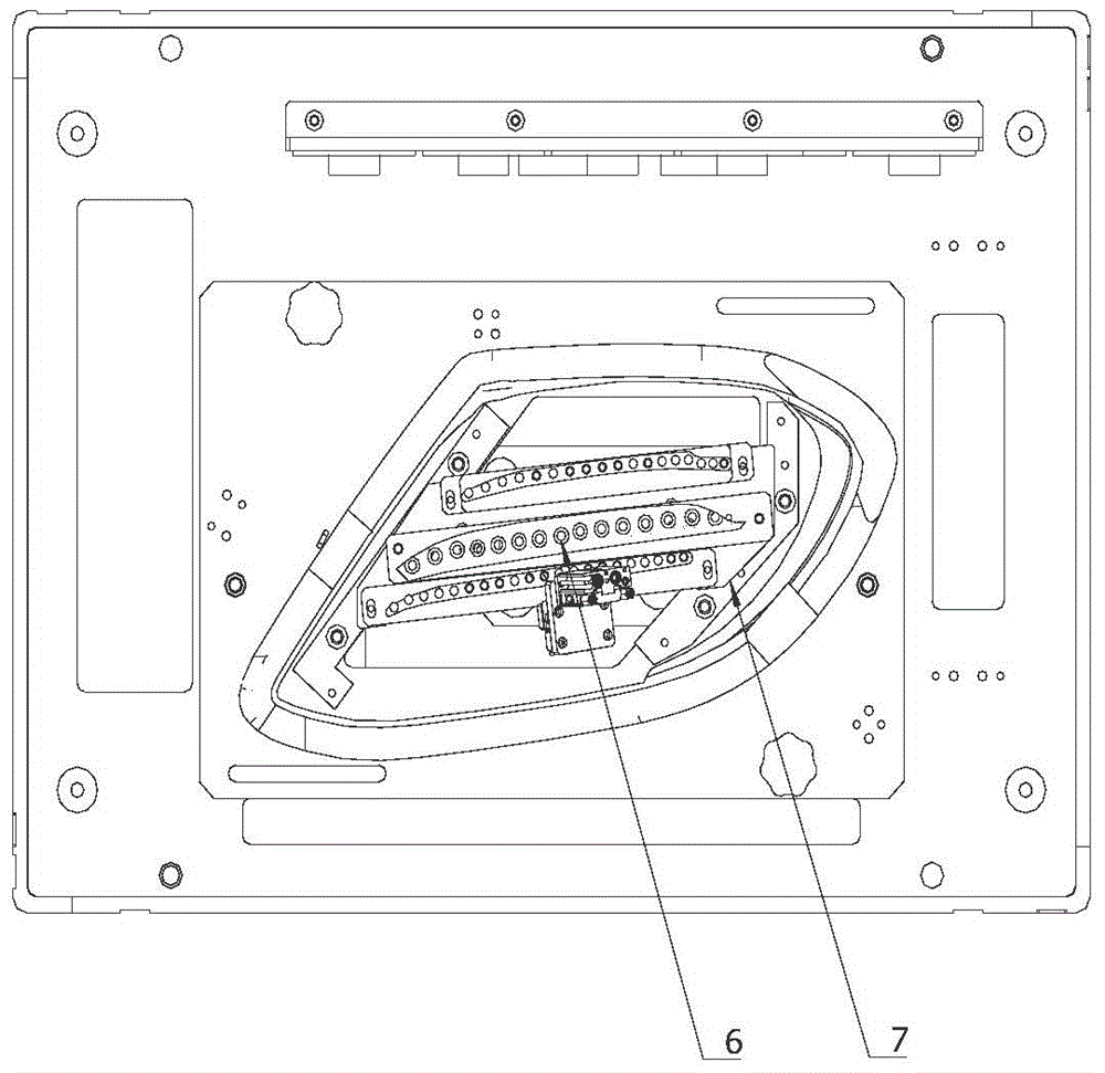
[0012] Referring to the accompanying drawings, a photosensitive sensor-based LED light detection mechanism for car lights includes a fixture carrier plate, on which a car light fixture and a PCB circuit board are fixedly installed, and an LED car light is installed on the car light fixture. A position adjustment mechanism is installed on the plate, and the position adjustment mechanism is equipped with a light guide element and a photosensitive sensor. The LED lamp is connected to the lamp power supply device through the lamp power plug, and the lamp power supply device is connected to the power module; the position adjustment mechanism will guide The light element extends into the interior of the LED car light and is close to the LED light. The light guide element exports the light of the corresponding LED light to the receiving end of the photosensitive sensor. The LED light will trigger the photosensitive sensor, and the photosensitive sensor transmits the output signal to th...
PUM
 Abstract
Description
Claims
Application Information
PatSnap Eureka turns technology decisions into work you can execute. Powered by our Innovation Knowledge Graph, it runs expert workflows across engineering, life sciences, materials and intellectual property. Get your review-ready output in minutes.


