
Method and system implementing spatially modulated excitation or emission for particle characterization with enhanced sensitivity

a particle and spatial modulation technology, applied in the direction of material analysis through optical means, instruments, disinfection, etc., can solve the problems of low signal-to-noise ratio (snr), requires sophisticated and bulky optics, and the signal-to-noise ratio is lower than desired

Active Publication Date: 2008-07-31
XEROX CORP
View PDF101 Cites 87 Cited by
  • Summary
  • Abstract
  • Description
  • Claims
  • Application Information

AI Technical Summary

Benefits of technology

The patent describes a method and system for characterizing particles by creating a spatially modulated excitation region and observing the time modulated signals that result. The signals can be detected using a pixelated detector or a spectrometer, and the particles can be counted and sorted based on the signals. The system can include a channel for moving the particles and an optical element to pattern the light. The technical effects of the patent include improved accuracy and efficiency in particle analysis and detection, as well as improved accuracy in DNA sequencing.

Problems solved by technology

Methods for particle characterization (which generally relates to detection as well as other useful characterizations such as location / position determination, particle counting and cell sorting) often suffer from a low signal-to-noise ratio (SNR), since the signal obtained from the particle (in general: a small object) is typically weak in comparison to the background.
However, it requires sophisticated and bulky optics to ensure suitably sized excitation and detection volumes.
Moreover, the resultant signal-to-noise ratios are lower than desired.

Method used


Image

  • Method and system implementing spatially modulated excitation or emission for particle characterization with enhanced sensitivity
  • Method and system implementing spatially modulated excitation or emission for particle characterization with enhanced sensitivity
  • Method and system implementing spatially modulated excitation or emission for particle characterization with enhanced sensitivity

Examples


Embodiment Construction

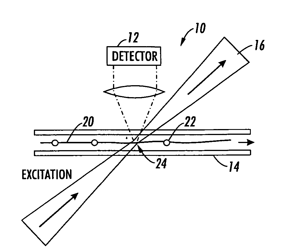
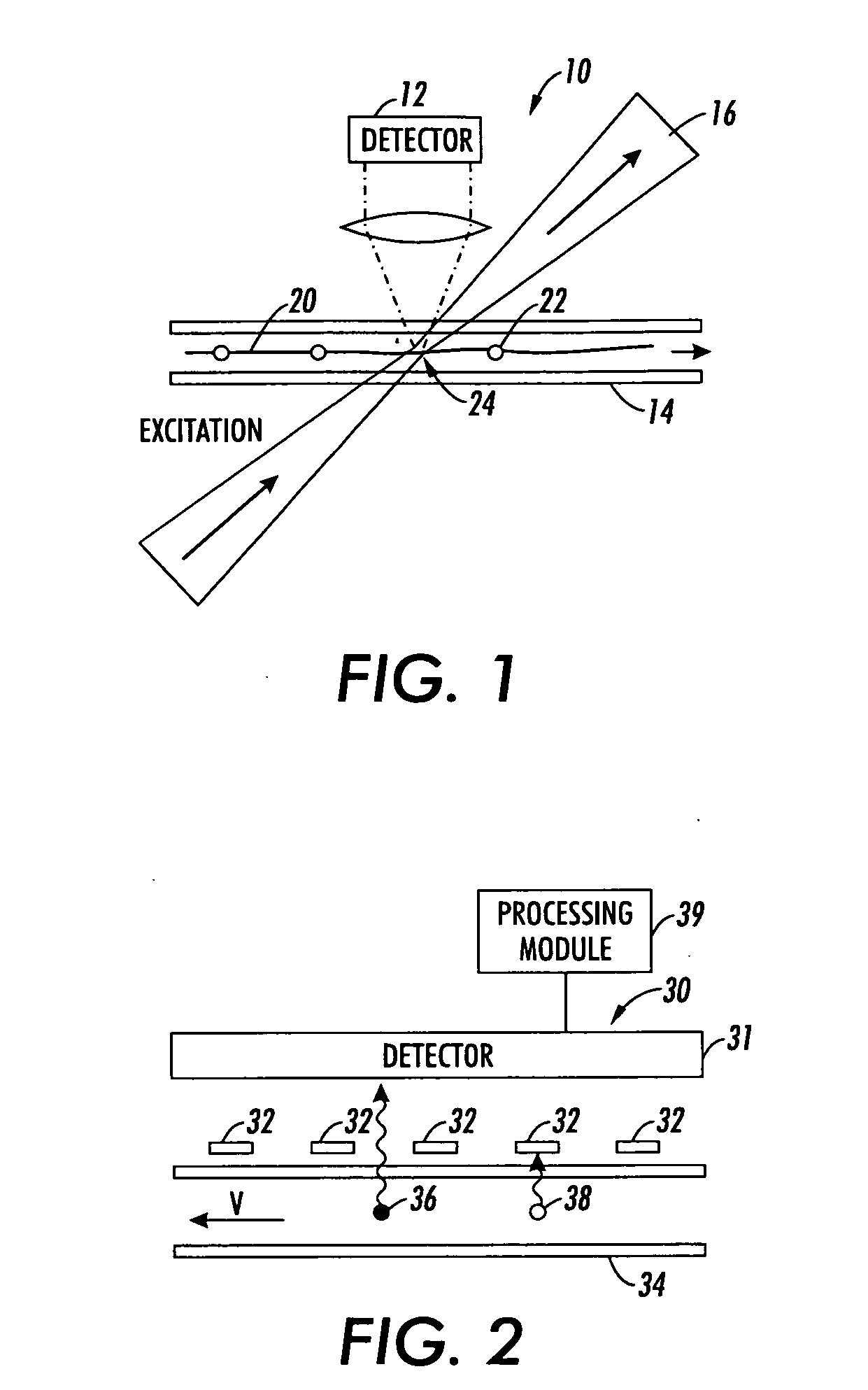
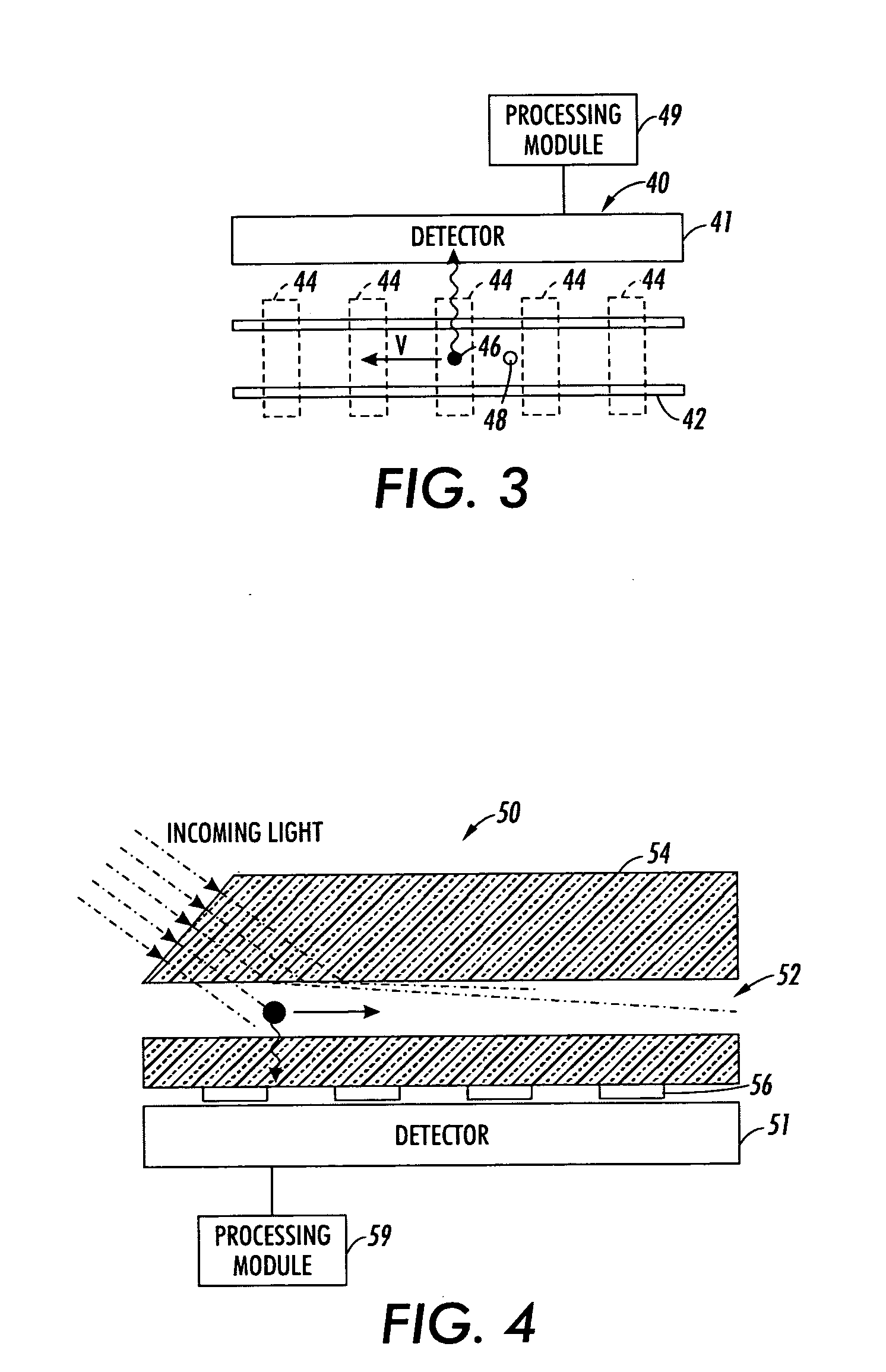
[0053]This patent application describes a method and a system to improve the signal-to-noise ratio during particle characterization by implementing a phase sensitive technique which allows for clearly distinguishing between the signals from the particle and the background. The method is based on the deliberate introduction of controlled relative movement between the particle and the environment. The combination of, for example, the moving particle and a conditioned environment results in a time modulated signal. A monitored response comprises a noisy background signal and the modulated signal, with a well defined time dependence attributable to the particle. Both hardware and software solutions can be applied to extract the signal attributed to the particle.

[0054]It should be understood that the signal attributed to the particle can then be used in characterizing the particle for a variety of different applications, including detection, location / position determination, and cell sort...


PUM

PropertyMeasurementUnit
volumeaaaaaaaaaa
frequencyaaaaaaaaaa
modulation frequencyaaaaaaaaaa

Abstract

A method and system for using spatially modulated excitation / emission and relative movement between a particle (cell, molecule, aerosol, . . . ) and an excitation / emission pattern are provided. In at least one form, an interference pattern of the excitation light with submicron periodicity perpendicular to the particle flow is used. As the particle moves along the pattern, emission is modulated according to the speed of the particle and the periodicity of the stripe pattern. A single detector, which records the emission over a couple of stripes, can be used. The signal is recorded with a fast detector read-out in order to capture the “blinking” of the particles while they are moving through the excitation pattern. This concept enables light detection with high signal-to-noise ratio and high spatial resolution without the need of expensive and bulky optics.

Description

CROSS REFERENCE TO RELATED PATENTS AND APPLICATIONS[0001]This application is related to U.S. application Ser. No. ______ (Attorney Docket No. 20060252-US-NP / XERZ 2 01398), entitled “Method and System for Evaluation of Signals Received from Spatially Modulated Excitation and Emission to Accurately Determine Particle Positions and Distances”, filed on even date herewith.BACKGROUND[0002]Methods for particle characterization (which generally relates to detection as well as other useful characterizations such as location / position determination, particle counting and cell sorting) often suffer from a low signal-to-noise ratio (SNR), since the signal obtained from the particle (in general: a small object) is typically weak in comparison to the background. This is particularly true in connection with optical methods of particle characterization. The low signal-to-noise ratio is also particularly noteworthy in cases of detection of individual particles such as a cell, an aerosol, a molecule,...

Claims


Application Information

Patent Timeline
Patent Type & Authority Applications(United States)
IPC IPC(8): A61L2/28G01N33/00G01N21/75G01N21/76
CPCG01N15/1427G01N15/147G01N2015/1447Y10T436/17G01N21/6486Y10T436/143333G01N2015/1454
Inventor BASSLER, MICHAELKIESEL, PETERSCHMIDT, OLIVERJOHNSON, NOBLE M.
Owner XEROX CORP
Learn More