Method to determine and adjust the alignment of the transmitter and receiver fields of view of a LIDAR system

Inactive Publication Date: 2006-06-20
NAT TECH & ENG SOLUTIONS OF SANDIA LLC
View PDF7 Cites 90 Cited by
  • Summary
  • Abstract
  • Description
  • Claims
  • Application Information

AI Technical Summary

Problems solved by technology

Although the initial alignment of all of the transmitter and receiver optics can be performed in a laboratory using precision optical alignment tooling, (interferometers,

Method used


Image

  • Method to determine and adjust the alignment of the transmitter and receiver fields of view of a LIDAR system
  • Method to determine and adjust the alignment of the transmitter and receiver fields of view of a LIDAR system
  • Method to determine and adjust the alignment of the transmitter and receiver fields of view of a LIDAR system

Examples


Embodiment Construction

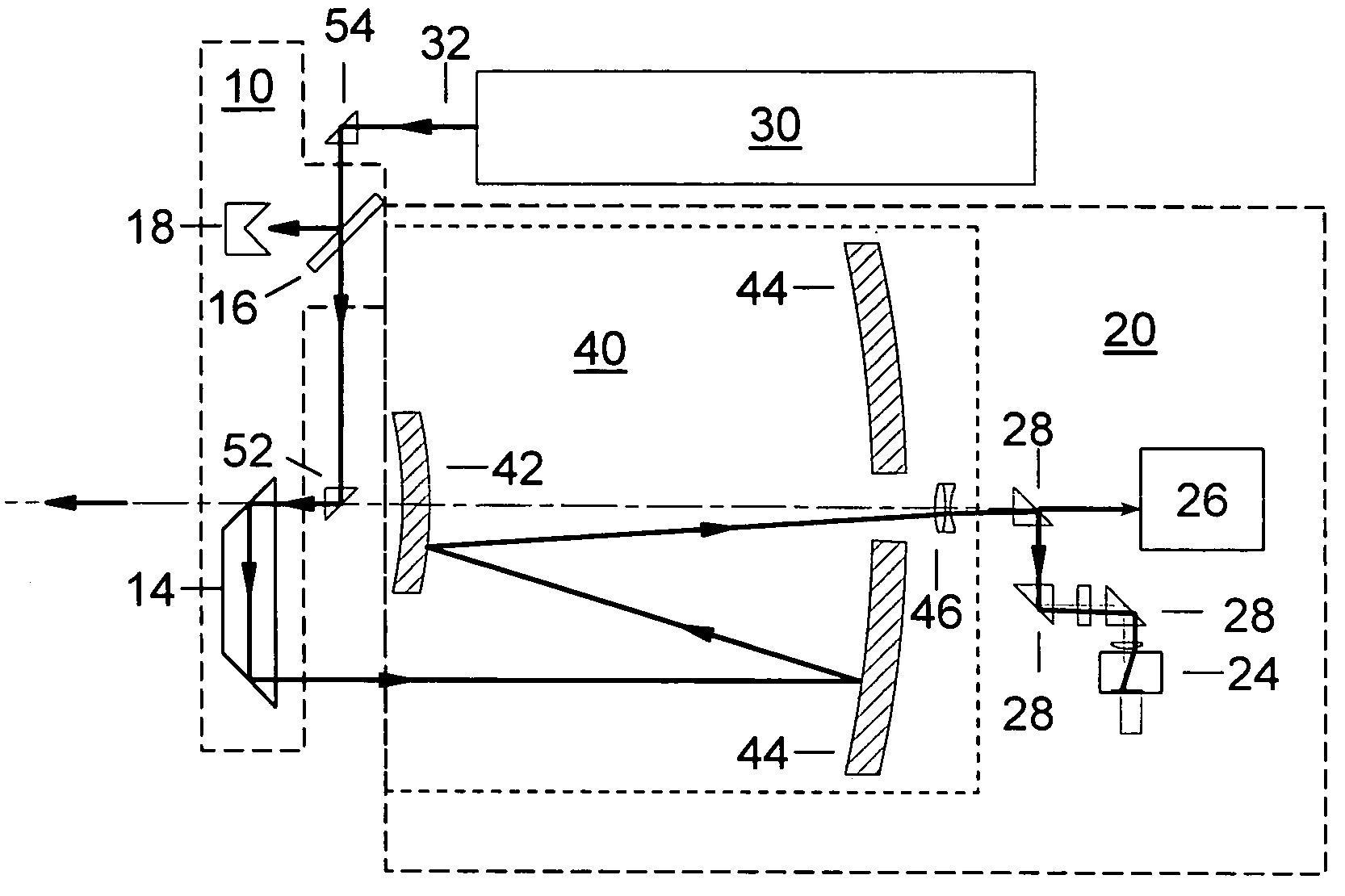
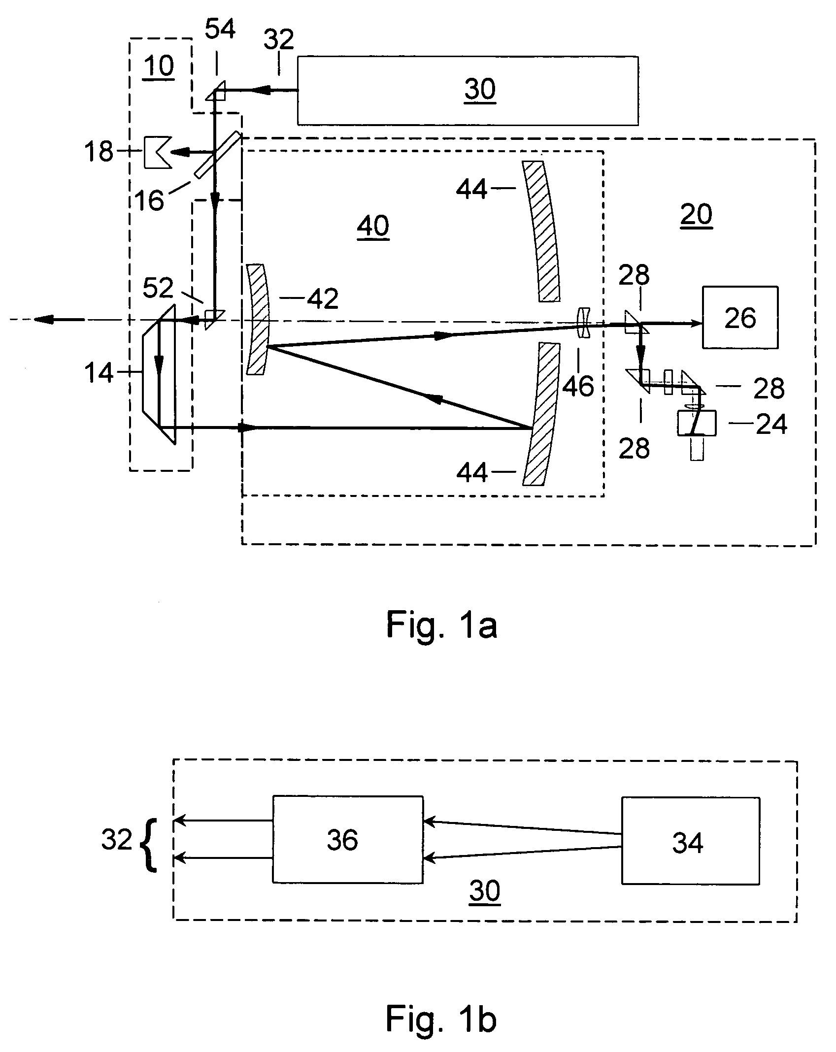
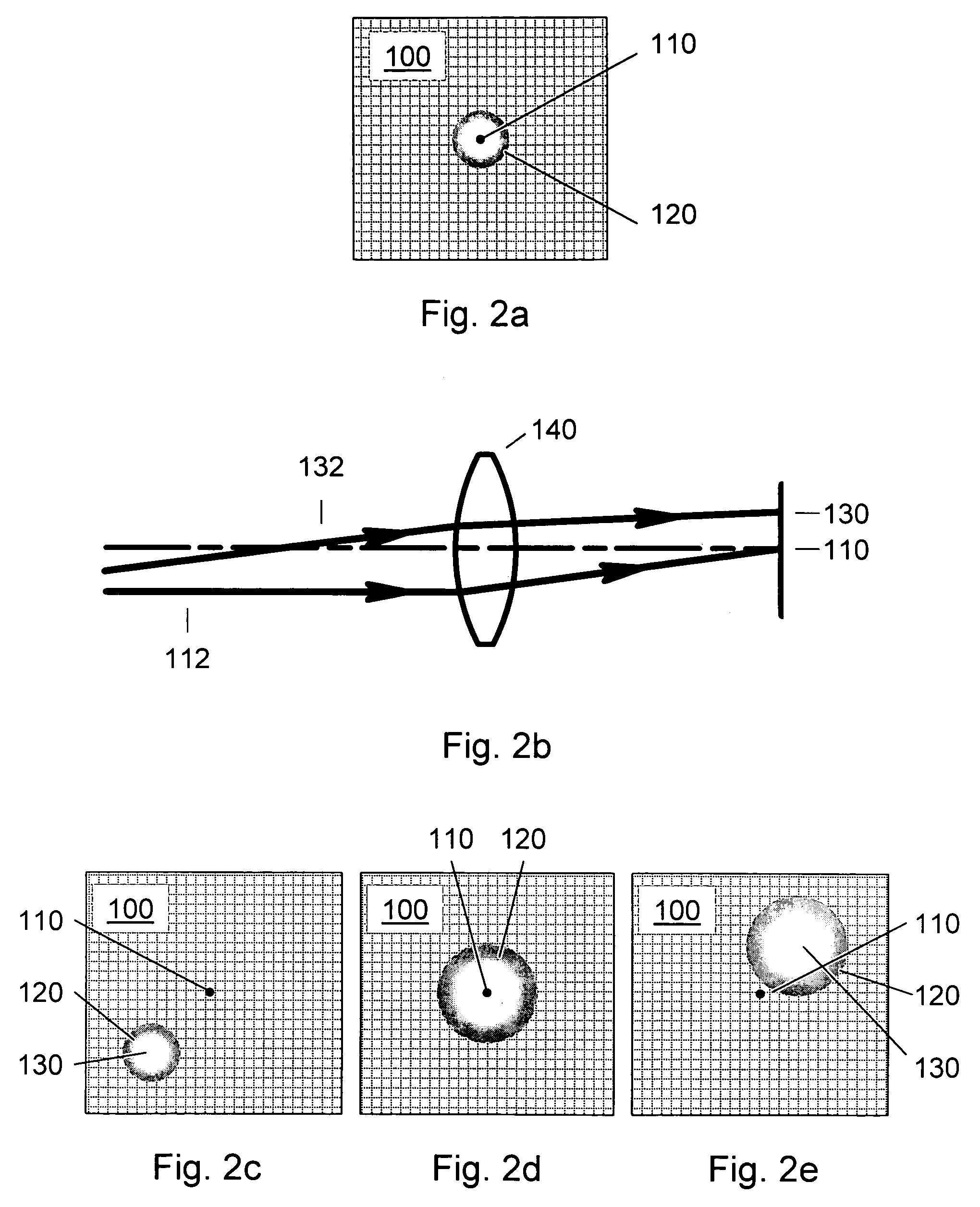
[0013]This invention is a method to determine the alignment of the transmitter and receiver fields of view of a light detection and ranging (LIDAR) system. Additionally, this method can be employed to determine the far-field intensity distribution of the transmitter beam, as well as the variations in transmitted laser beam pointing as a function of time, temperature, or other environmental variables that may affect the co-alignment of the LIDAR system components. In order to achieve proper alignment of the transmitter and receiver optical systems when a LIDAR system is being used in the field, this method employs a laser-beam-position-sensing detector as an integral part of the receiver optics of the LIDAR system.

[0014]In one embodiment of the method, this position-sensing detector is used in combination with an attenuator-and-reflector assembly. The co-alignment of the transmitted laser beam from the laser transmitter system can be checked with respect to the receiver telescope fie...


PUM


Abstract

A method to determine the alignment of the transmitter and receiver fields of view of a light detection and ranging (LIDAR) system. This method can be employed to determine the far-field intensity distribution of the transmitter beam, as well as the variations in transmitted laser beam pointing as a function of time, temperature, or other environmental variables that may affect the co-alignment of the LIDAR system components. In order to achieve proper alignment of the transmitter and receiver optical systems when a LIDAR system is being used in the field, this method employs a laser-beam-position-sensing detector as an integral part of the receiver optics of the LIDAR system.

Description

[0001]This application claims the benefit of U.S. Provisional Application No. 60 / 517,344, filed on Nov. 4, 2003.[0002]The United States Government has rights in this invention pursuant to Department of Energy Contract No. DE-AC04-94AL85000 with Sandia CorporationBACKGROUND OF THE INVENTION[0003]This invention relates to a method for operating a laser-based detection system and more particularly to a method to determine the alignment of the transmitter and receiver fields of view of a light detection and ranging (LIDAR) system. LIDAR systems are used to measure distances and properties of distant objects. Among the many uses of LIDAR are the measurement of clouds, aerosols, water vapor, pollutants, and forest growth and health. In a LIDAR system, the alignment of a transmitted laser beam with respect to the field of view of the receiver optics is critical, particularly if the laser beam divergence is a large fraction of the total field of view of the receiver optical system. If the f...

Claims


Application Information

Patent Timeline
IPC IPC(8): G01B11/26G01C1/00
CPCG01S7/4972
Inventor SCHMITT, RANDAL L.HENSON, TAMMY D.KRUMEL, LESLIE J.HARGIS, JR., PHILIP J.
Owner NAT TECH & ENG SOLUTIONS OF SANDIA LLC
Why Eureka
Try Eureka