Method and apparatus for dielectrophoretic separation

a dielectrophoretic and separation method technology, applied in the direction of liquid/fluent solid measurement, fluid pressure measurement, peptide, etc., can solve the problems of difficult fabrication process, limited operation of other devices, and high throughput separation device creation

Inactive Publication Date: 2006-11-23
RGT UNIV OF CALIFORNIA
View PDF8 Cites 37 Cited by
  • Summary
  • Abstract
  • Description
  • Claims
  • Application Information

AI Technical Summary

Benefits of technology

[0015] In another aspect, the device described above includes an insulator disposed between the first conductor and the second conductor in the separation zone. For example, the insulat

Problems solved by technology

Separation using DEP has been demonstrated, but because the DEP force decays rapidly as the distance from typical planar electrode arrays increases, there have been difficulties in creating high throughput separation devices.
There is a problem, however, with existing DEP-based separation devices because many require high voltages to effectuate particle separation.
Still other devices are limited in their operation because of the quick decay of the DEP force from commonly used planar electrodes.
Other devices involve difficult fabrication processes such as etching through a wafer or the use of transparent conductors.
However, even when using 3D electrodes, it is difficult to create a high efficiency separation device bec

Method used


Image

  • Method and apparatus for dielectrophoretic separation
  • Method and apparatus for dielectrophoretic separation
  • Method and apparatus for dielectrophoretic separation

Examples


Embodiment Construction

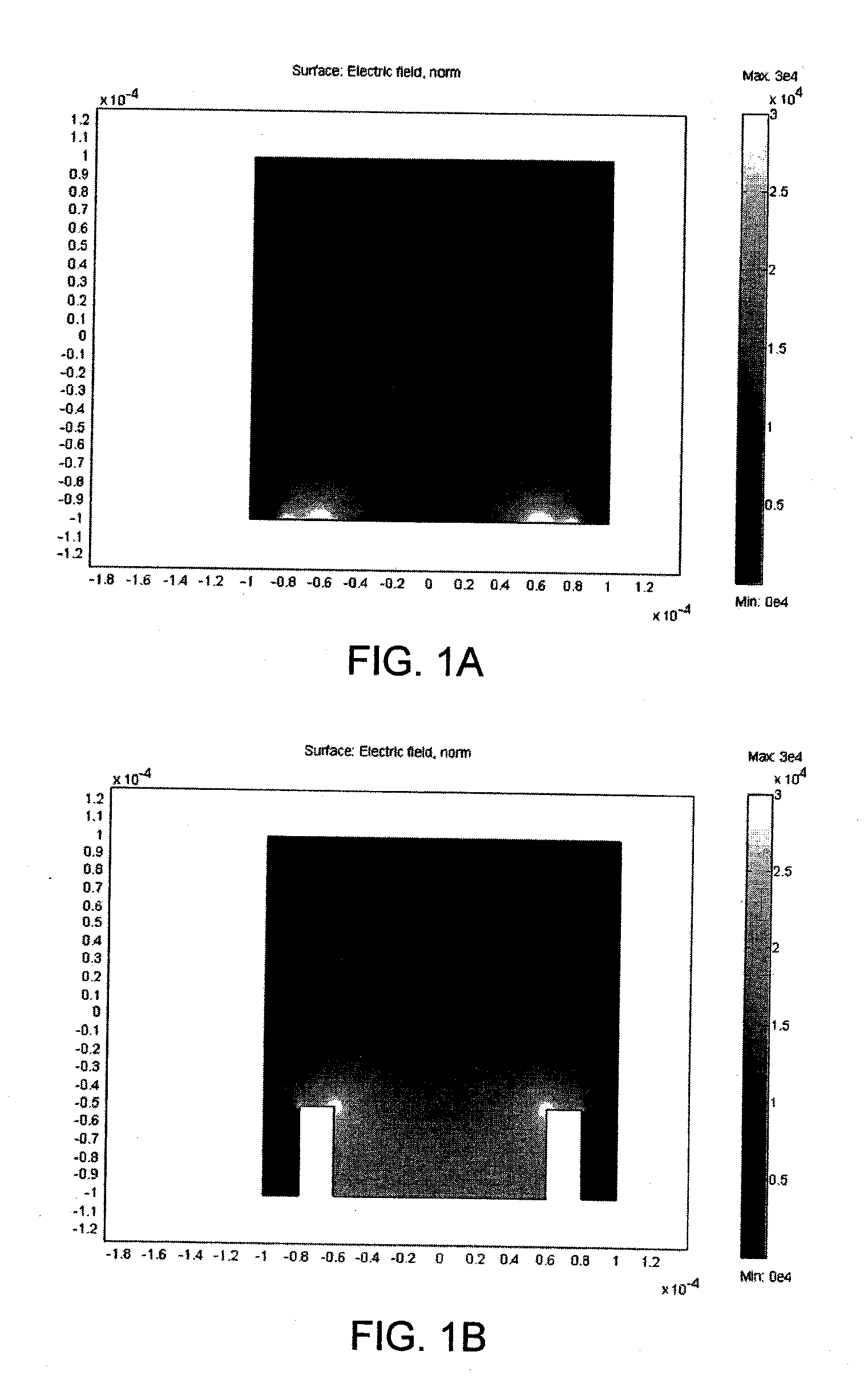
[0030]FIG. 1A graphically illustrates the results of a computer simulation of the electric field present in de-ionized water (DI) in which two planar electrodes have been placed. The modeled electrodes had diameters of 50 μm and a center-to-center distance of 140 μm. A voltage of + / −30V was applied to the electrodes. As seen in FIG. 1A, the electric field generated by the electrodes is concentrated at or near the planar electrodes. The electric field is, however, relatively weak or low between the adjacent electrodes.

[0031] Although there has been some success in particle separation using planar electrodes, most designs have suffered from the problem of low throughput. The problem with traditional methods of using planar microelectrodes is that the DEP force, which is proportional to ∇|R|2, rapidly decays as the distance from the planar electrodes increases. This is one of the limitation that has prevented dielectrophoresis from being widely used in high volume applications. There ...


PUM

PropertyMeasurementUnit
Forceaaaaaaaaaa
Flow rateaaaaaaaaaa
Electric potential / voltageaaaaaaaaaa

Abstract

A dielectrophoretic separation device includes a chamber including an inlet and an outlet disposed between the inlet and the outlet. A plurality of three dimensional electrodes are disposed in within the chamber. The electrodes may take the form of a wire or semi-cylindrical conductors disposed on a substrate. At least some of the electrodes include smooth surfaces so as to create an electric field (in response to an applied alternating current) that has a low strength in a region disposed away from the electrodes and an electric field having a high fields strength in a region between adjacent electrodes. Particulate matter or other species experiencing a positive DEP force may be separated and collected in the gaps or regions formed between adjacent electrodes.

Description

REFERENCE TO RELATED APPLICATIONS [0001] This Application claims priority to U.S. Provisional Patent Application No. 60 / 682,562 filed on May 19, 2005. U.S. Provisional Patent Application No. 60 / 682,562 is incorporated by reference as if set forth fully herein.STATEMENT REGARDING FEDERALLY SPONSORED RESEARCH AND DEVELOPMENT [0002] The U.S. Government may have a paid-up license in this invention and the right in limited circumstances to require the patent owner to license others on reasonable terms as provided for by the terms of Grant No. DMI-0428958 awarded by the National Science Foundation.FIELD OF THE INVENTION [0003] The field of the invention generally relates to methods and devices that use electrodes for creating an electric field gradient for dielectrophoretic separation processes. The field of the invention further relates to shaping of three-dimensional (“3D”) electrodes such that the fluid flow surrounding the 3D electrodes is highly correlated to the generated electric f...

Claims


Application Information

Patent Timeline
IPC IPC(8): B03C5/02
CPCB03C5/026B03C5/005
Inventor MADOU, MARC J.PARK, BENJAMIN Y.PARADISO, ALAN C.
Owner RGT UNIV OF CALIFORNIA
Why Eureka
Try Eureka