Magnetoelastic force sensors, transducers, methods, and systems for assessing bending stress

a technology of magnetic force and sensors, applied in the field of magnetic force sensors, can solve problems such as affecting the accuracy of ultimate sensors

Inactive Publication Date: 2012-11-22
MAGCANICA
View PDF3 Cites 38 Cited by
  • Summary
  • Abstract
  • Description
  • Claims
  • Application Information

AI Technical Summary

Benefits of technology

[0013]A new type of force sensor, having no excitation source and wherein in the absence of applied force the measured quantity is inherently zero, is described. The new sensor is a true transducer, in that it converts a portion of the mechanical work associated with the application of force to an elastically deformable member into a magnetic field, the intensity of which is linearly proportional to the applied force and whose polarity is reversed between push and pull forces. In its elementary form (FIG. 1), the new transducer consists of a thin wall tube of circumferentially remanently magnetized, magnetoelastically active material, supported as a beam, wherein the force (P) to be sensed is applied transverse to the tube's longitudinal axis. A magnetic field sensor (Hall effect device, magnetoresistor flux gate, etc.) oriented to sense radial fields, is mounted on or near the outside (inside) surface of the tube, on the diametral plane normal to P. Operation of this sensor will be shown to derive from subtle consequences of the distinctive stress distribution associated with flexure4, combined with the spin vector orientation distribution which characterizes the beam's remanent5 magnetization.

Problems solved by technology

Operation of such sensors obviously requires a source of cyclically varying exciting fields, the frequency, amplitude, and wave shape of which affect sensor performance Also, since the measured property changes from some non-zero quiescent value in response to the force, the force-to-property “transfer functions” of these types of sensors typically include an offset term, any inconstancy of which can impair the ultimate sensor accuracy.

Method used


Image

  • Magnetoelastic force sensors, transducers, methods, and systems for assessing bending stress
  • Magnetoelastic force sensors, transducers, methods, and systems for assessing bending stress
  • Magnetoelastic force sensors, transducers, methods, and systems for assessing bending stress

Examples


Embodiment Construction

A. Theory

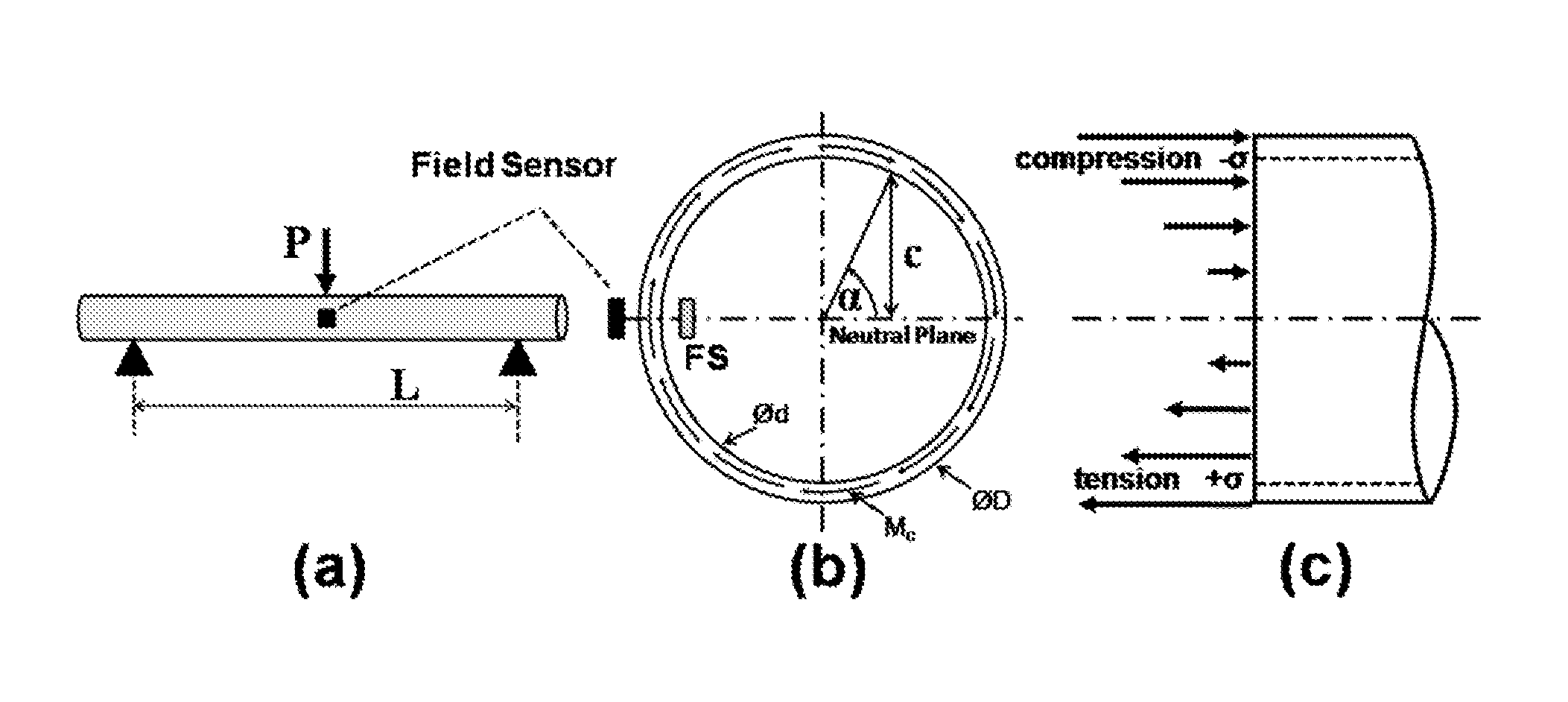
[0028]For the member, shown as a beam in FIG. 1(a), resting on two supports, distance L apart, the bending moment B, at the midpoint where P is applied, is found as B=PL / 4. Equilibrium demands that B at any location be resisted by the moment of the longitudinal (i.e., “normal”) stresses within the beam material and that the net force from such stresses be zero. These requirements are met in beams with cross sections having mirror image symmetry about a center line normal to both P and L, e.g., round tubular cross sections, by the symmetrical distribution of tensile (+ψ) and compressive (−ψ) stresses indicated in FIG. 1(c). The stress magnitude at distance c (FIG. 1(b)) from the beam's central plane (the “neutral axis”) is found as4: ψ=Bc / I, where I is the moment of inertia of the cross section about its diameter. For a tubular section with outside diameter D and inside diameter d, I=π (D4−d4) / 64. For a thin tube, wherein D≈d, c may be expressed with adequate precision in te...


PUM

PropertyMeasurementUnit
forceaaaaaaaaaa
bending stressaaaaaaaaaa
voltageaaaaaaaaaa

Abstract

A new type of magnetoelastic device for sensing force is described. It comprises of two elements: a circumferentially magnetized member comprised of magnetoelastically active material mounted as a beam and loaded by the force to be sensed, and a magnetic field sensor mounted at or near the member's surface, preferentially at or near a longitudinal location where the bending moment is maximum and at a circumferential location where the bending stress is zero. Flexural loading causes a variation of the circumferential magnetization with angular position. This variation is the source of free poles, the field from which is a measure of the applied force. Testing demonstrates that the field intensity is a linear analog of the experienced bending stress over a significant range of applied push and pull forces.

Description

FIELD OF THE INVENTION[0001]This invention concerns sensors and transducers for assessing bending stresses and measuring force on magnetized members and objects magnetized members are attached to, as well as systems and methods for making and using the same.BACKGROUND OF THE INVENTION[0002]1. Introduction[0003]The following description includes information that may be useful in understanding the present invention. It is not an admission that any such information is prior art, or relevant, to the presently claimed inventions, or that any publication specifically or implicitly referenced is prior art.[0004]2. Background[0005]Force sensors based on magnetomechanical effects typically derive their output signals from variation of a magnetic property of a magnetoelastically active “core” member with the stress caused by the force of interest. Thus, stress-induced changes in peak induction', coercivity, or permeability' have been suggested for sensing force. Operation of such sensors obvi...

Claims


Application Information

Patent Timeline
Patent Type & Authority Applications(United States)
IPC IPC(8): G01L1/12G06F19/00
CPCG01L3/103G01L1/125
Inventor GARSHELIS, IVAN J.TOLLENS, STIJN P. L.
Owner MAGCANICA
Why Eureka
Try Eureka