
Three-phase sine wave inverter control method having high DC voltage utilization ratio

A technology of high DC voltage and control method, applied in the direction of converting AC power input to DC power output, output power conversion device, electrical components, etc., can solve the difficulty of on-line voltage regulation of switch point preset PWM The problem of high utilization rate of DC voltage of PWM type PWM is achieved, and the effect of expanding the normal working voltage range, high utilization rate of DC voltage and improving reliability is achieved.

Inactive Publication Date: 2015-10-07
NORTHWESTERN POLYTECHNICAL UNIV
View PDF5 Cites 3 Cited by
  • Summary
  • Abstract
  • Description
  • Claims
  • Application Information

AI Technical Summary

Problems solved by technology

Due to the combination of switch point preset PWM and unipolar SPWM, the technical problem of difficult online voltage regulation of switch point preset PWM is solved, and at the same time, the characteristic of high DC voltage utilization rate of switch point preset PWM is retained

Method used


Image

  • Three-phase sine wave inverter control method having high DC voltage utilization ratio
  • Three-phase sine wave inverter control method having high DC voltage utilization ratio
  • Three-phase sine wave inverter control method having high DC voltage utilization ratio

Examples


Embodiment Construction

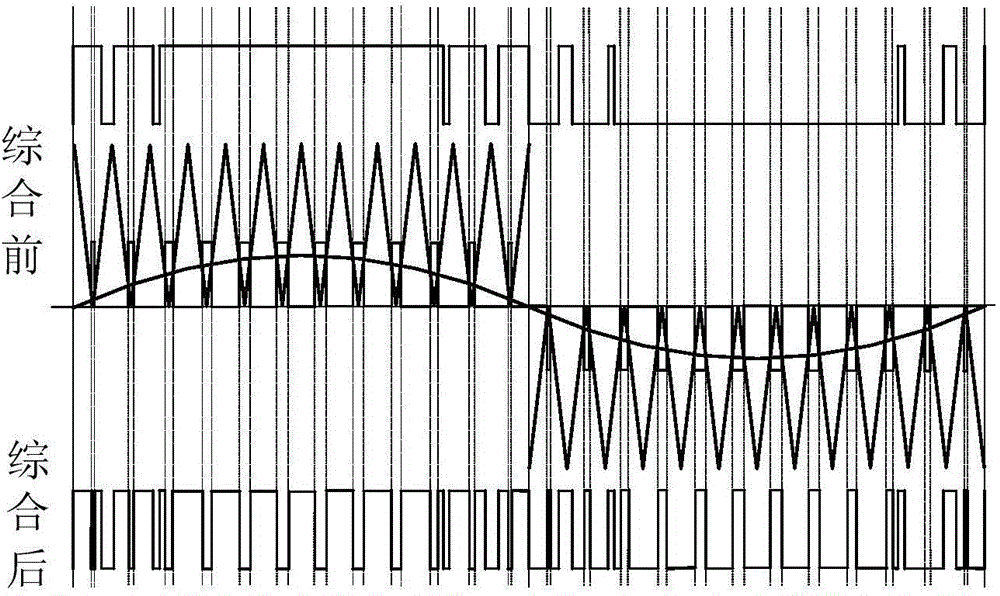
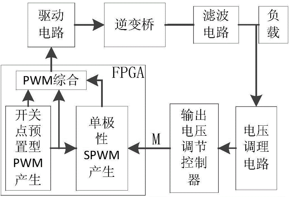
[0025] Reference Figure 1-3 . The specific steps of the three-phase sine wave inverter control method with high DC voltage utilization rate of the present invention are as follows:

[0026] Determine the number of switching points m within the 1 / 4 cycle of the preset PWM wave, and use θ for the switching angles respectively 1 , Θ 2 ,..., θ m Indicates that taking the DC side voltage of the inverter bridge as the unit 1, the n-th harmonic voltage amplitude U in the PWM wave n for:

[0027] U n = 4 nπ [ X i = 1 m ( - 1 ) i cos n θ i + 0.5 ] m is even

[0028] U n = 4 nπ [ X i = 1 m ( - 1 ) i + 1 cos nθ i - 0.5 ] m is odd

[0029] According to fundamental wave amplitude U 1 Optimize the maximum or low-order harmonic content to zero on the principle to obtain the switching angle value within 1 / 4 cycle, and then determine the entire cycle according to the ch...


PUM


Abstract

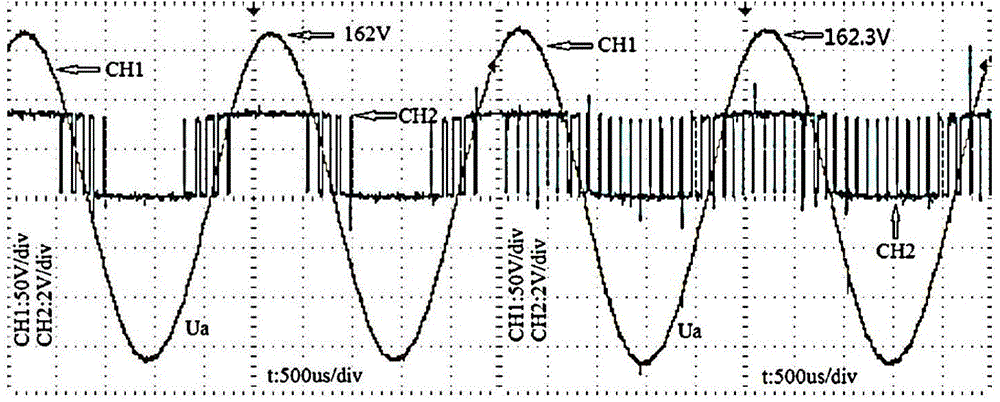
The invention discloses a three-phase sine wave inverter control method having a high DC voltage utilization ratio, and aims to solve the technical problem of difficulty in online voltage regulation in the prior art. The technical scheme is that through the mixing of switching node preset PWM and unipolar SPWM, the purpose of regulating output voltage by adjusting the modulation ratio of a unipolar SPWM wave is achieved; and meanwhile, when the modulation ratio M of the unipolar SPWM wave is equal to 0, the control method provided by the invention is degraded to the switching node preset PWM, thereby retaining the characteristic of high DC voltage utilization ratio. With the combination of the switching node preset PWM and the unipolar SPWM, the technical problem of difficulty in online voltage regulation for the switching node preset PWM is solved. According to the invention, the output voltage fundamental voltage amplitude and the modulation ratio M are in linear relationship that U1=-1.7299*M+1.0134, and thus the inverter applying the method is allowed to work at low voltage.

Description

Technical field [0001] The invention relates to a three-phase sine wave inverter control method, in particular to a three-phase sine wave inverter control method with high direct current voltage utilization rate. Background technique [0002] Among the commonly used three-phase bridge inverter control methods, the PWM control methods include pure sine modulation SPWM, third harmonic injection PWM and switching point preset PWM. [0003] Literature 1 "Power Electronics Technology, 2000, p150-162" describes the characteristics of the pure sine modulation SPWM control method. The main implementation method is to determine the high and low levels of the output PWM through the real-time comparison of high-frequency triangle waves and sine waves. This method Simple and easy to implement, but its DC voltage utilization rate is only 0.866. [0004] Literature 2 "The use of harmonic distortion to increase the output voltage of a three-phase PWM inverter, Industry Applications, IEEE Transacti...

Claims


Application Information

Patent Timeline
Patent Type & Authority Applications(China)
IPC IPC(8): H02M7/5387
Inventor 郑先成宋勇刚吴小华张晓斌李伟林宋丹
Owner NORTHWESTERN POLYTECHNICAL UNIV
Learn More