A Main Circuit Topology of Medium and High Voltage Direct Hanging Static Synchronous Var Compensator

A static synchronous, topological structure technology, applied in the direction of reactive power compensation, reactive power adjustment/elimination/compensation, etc., can solve the high and low voltage off-grid accidents of large-scale new energy power plants, cannot meet the dynamic and stable operation requirements of AC systems, Problems such as poor linearity of reactive power compensation can achieve high DC voltage utilization, improve grid adaptability, and improve survivability

Active Publication Date: 2016-04-20
STATE GRID CORP OF CHINA +4
View PDF2 Cites 0 Cited by
  • Summary
  • Abstract
  • Description
  • Claims
  • Application Information

AI Technical Summary

Problems solved by technology

[0003] Fixed reactive power compensation device and phase-controlled dynamic reactive power compensation device are the two most mature reactive power compensation methods at this stage, but due to the introduction of high-speed railways, a large number of nonlinear loads and active loads in the system Dramatic changes require the system to respond more quickly to reactive power and have a good harmonic filtering function. The conventional fixed reactive power compensation method based on switching capacitors or reactors has poor linearity of reactive power compensation and may cause system Problems such as harmonic amplification and overvoltage have been unable to meet the current needs of rapid reactive power response and dynamic and stable operation of AC systems
[0004] Static synchronous compensator (STATCOM) based on voltage source commutation is a new type of device with reactive power compensation and harmonic suppression that has developed rapidly in recent years. This compensator has been quite mature abroad, but has not yet realized the key The technological breakthrough is mainly the converter topology technology applied in the medium and high voltage field. The STATCOM main circuit topology that has been engineered at this stage is generally designed with a power frequency transformer. This method has the disadvantages of large equipment investment, large area occupation, and High cost and long production cycle
In addition, there is a topology based on cascaded multi-level, which has problems such as large device investment and relatively complicated control, and the current application voltage level is low, generally 10kV and below
[0005] At this stage, due to the injection of large-scale new energy power, the power fluctuation and randomness are strong, the system has insufficient standby reactive power capacity, and the power quality problem and system voltage stability problem are gradually extended to the AC transmission network, which seriously affects the stable operation of large systems. , and may even lead to high and low voltage off-grid accidents in large-scale new energy power plants

Method used


Image

  • A Main Circuit Topology of Medium and High Voltage Direct Hanging Static Synchronous Var Compensator
  • A Main Circuit Topology of Medium and High Voltage Direct Hanging Static Synchronous Var Compensator
  • A Main Circuit Topology of Medium and High Voltage Direct Hanging Static Synchronous Var Compensator

Examples


Embodiment

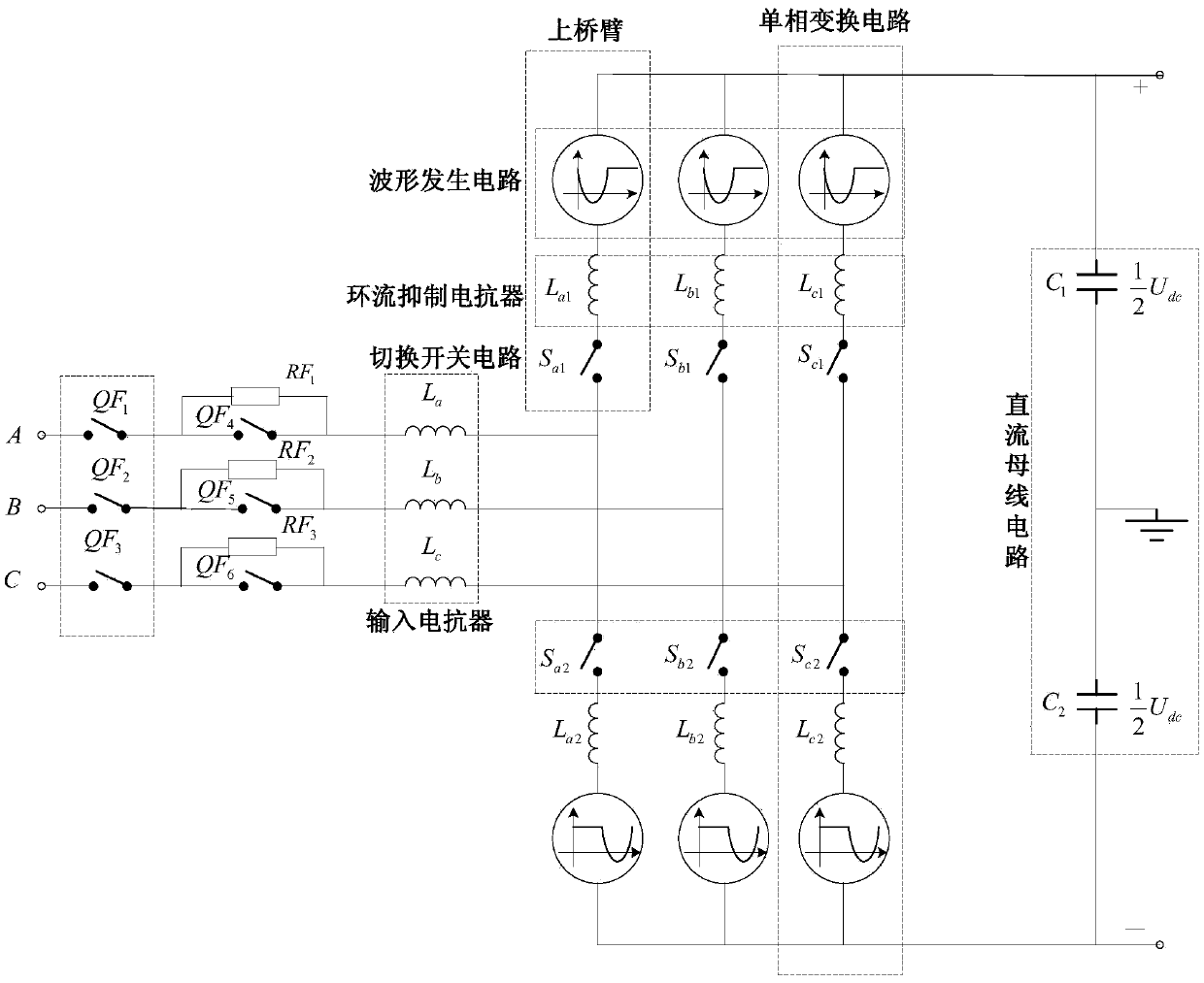
[0056] Such as figure 1 , the main circuit topology of the medium and high voltage direct-hanging static var compensator is composed of three single-phase conversion circuits, each single-phase conversion circuit is composed of upper and lower bridge arms, and each bridge arm is composed of a waveform generating circuit, a circulating current suppression reactance device and switch circuit. In the upper bridge arm, one end of the waveform generating circuit is connected together to form the positive pole of the common DC bus, and the other end is connected to the circulating current suppression reactor L a1 , L b1 , L c1 Connection; circulating current suppression reactor L a1 , L b1 , L c1 The other end of the switch with the toggle switch S a1 ,S b1 ,S c1 connect. In the single-phase conversion circuit, the topological structure of the upper and lower bridge arms is symmetrically distributed. The waveform generation circuit, the circulating current suppression react...


PUM


Abstract

The invention provides a main circuit topology structure of a medium-high voltage directly suspended type static synchronous reactive compensator. The main circuit topology structure comprises single-phase conversion circuits, a public direct-current bus circuit, current conversion electric reactors and starting circuits. The single-phase conversion circuit is connected with the public direct-current bus circuit in parallel, then the output ends of the single-phase conversion circuits are connected with the current conversion electric reactors, and the current conversion electric reactors are connected into an alternating-current power grid through the starting circuits. The main circuit topology structure has the advantages that functions of reactive voltage support, harmonic pollution regulation, chugging damping and others can be achieved, the medium-high voltage alternating-current power grid can be directly suspended, output waveforms are good in quality, the frequency of switching action is low, the number of needed switching elements is relatively small, the utilization rate of direct-current voltage is high, and fault currents on the direct-current side can be suppressed. The number of filters on the alternating-current side can be reduced, earlier state investment cost and control complexity of the compensator can be reduced, the energy conversion efficiency of the reactive compensator can be improved, the fault viability of the reactive compensator can be improved, the utilization rate per unit of the reactive compensator can be increased, the range of application occasions can be enlarged, and functions of the reactive compensator can be expanded.

Description

technical field [0001] The invention relates to a topological structure, in particular to a main circuit topological structure of a medium-high voltage direct-mounted static synchronous reactive power compensator. Background technique [0002] Reactive power compensation is of great significance to the AC power system, and the balance of reactive power directly affects the safety, stability and economic operation of the power system. Appropriate reactive power compensation can solve the problems of overvoltage and system stability caused by reactive power deficiency and reactive power surplus in different operating modes of the power system. [0003] Fixed reactive power compensation device and phase-controlled dynamic reactive power compensation device are the two most mature reactive power compensation methods at this stage, but due to the introduction of high-speed railways, a large number of nonlinear loads and active loads in the system Dramatic changes require the sys...

Claims


Application Information

Patent Timeline
Patent Type & Authority Patents(China)
IPC IPC(8): H02J3/18
CPCY02E40/30
Inventor 王志冰姚良忠迟永宁王晓弘李琰吕鸣镝孙蔚吴婧赵琳王真汤海雁张占奎魏林君苏媛媛
Owner STATE GRID CORP OF CHINA
Why Eureka
Try Eureka