
Ceiling fan lamp control method

A control method and technology for ceiling fan lamps, which are applied in the direction of electric lamp circuit arrangement, lighting devices, light sources, etc., can solve problems such as poor anti-interference ability and increase of control lines.

Inactive Publication Date: 2015-10-07
HUNAN UNIV OF TECH
View PDF3 Cites 2 Cited by
  • Summary
  • Abstract
  • Description
  • Claims
  • Application Information

AI Technical Summary

Problems solved by technology

But this method also needs to increase the control line, and the anti-interference ability is poor

Method used


Image

  • Ceiling fan lamp control method
  • Ceiling fan lamp control method
  • Ceiling fan lamp control method

Examples


Embodiment Construction

[0075] The present invention will be described in further detail below with reference to the accompanying drawings and examples, but the embodiments of the present invention are not limited thereto.

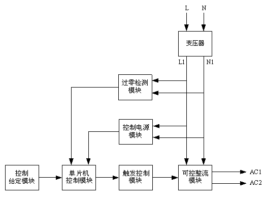
[0076] Realize the device system structural block diagram of the inventive method as figure 1 As shown, it consists of a rectifier control unit and a ceiling fan light control unit. The rectification control unit receives single-phase 220V AC power from phase line input terminal L and neutral line input terminal N, and outputs controllable rectification voltage from the first controllable rectification output terminal AC1 and the second controllable rectification output terminal AC2. The control unit of the ceiling fan lamp inputs the controllable rectification voltage from the first controllable rectification input terminal AC1 and the second controllable rectification input terminal AC2 to control the ceiling fan lamp.

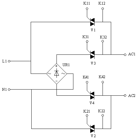
[0077] The structure of the rectifier control unit is as...


PUM


Abstract

A ceiling fan lamp control method is implemented through an apparatus formed by a rectification control unit and a ceiling fan lamp control unit. The rectification control unit inputs a single-phase 220V AC power source, outputs a controllable rectification voltage that has undergone voltage reduction by a transformer, and sends in the controllable rectification voltage a ceiling fan lamp control signal that includes a ceiling fan speed grade and a lamp brightness grade. The ceiling fan lamp control signal includes guide waves formed by rectification waves with multiple power frequency periods and AC waves with one power frequency period, and also data waves formed by multiple power frequency periods. The ceiling fan lamp control unit inputs the controllable rectification voltage containing the ceiling fan lamp control signal, and controls the ceiling fan speed and the lamp brightness. The method does not need a remote controller, a control line needs not to be laid additionally, a single-phase power line is directly utilized to transmit the ceiling fan lamp control signal, and a ceiling fan lamp can be controlled and adjusted in a remote manner.

Description

technical field [0001] The invention relates to a ceiling fan lamp control technology, in particular to a ceiling fan lamp control method. Background technique [0002] When both the speed of the ceiling fan and the brightness of the lamp in the ceiling fan lamp need to be adjusted and controlled, the usual methods are: [0003] One is to use remote control. The drive control circuit of the ceiling fan light is equipped with a remote control receiving device, which can adjust the speed and light of the ceiling fan light through the remote control. The disadvantage is that it needs to be equipped with a remote control, which is troublesome to manage and easy to lose. [0004] The second is the use of digital control technology. For example, use the RS-485 bus to control the ceiling fan lamp. This solution is advanced in technology, but the cost is high. In addition to power lines, the system also needs to lay out digital control buses. [0005] The third is to use analog ...

Claims


Application Information

Patent Timeline
Patent Type & Authority Applications(China)
IPC IPC(8): H05B37/02
Inventor 凌云曾红兵王兵郭艳杰唐文妍彭杲
Owner HUNAN UNIV OF TECH
Learn More