
Method and device for joining members

A technology for joining components and components, applied in welding equipment, non-electric welding equipment, metal processing equipment, etc., to achieve the effect of large material quality range, large material thickness range, and avoidance of tolerance chain problems

Inactive Publication Date: 2015-10-14
BAYERISCHE MOTOREN WERKE AG
View PDF6 Cites 7 Cited by
  • Summary
  • Abstract
  • Description
  • Claims
  • Application Information

AI Technical Summary

Problems solved by technology

With punch riveting, only materials with a quality within a certain lower limit and only within a certain thickness range can be joined

Method used


Image

  • Method and device for joining members
  • Method and device for joining members
  • Method and device for joining members

Examples


Embodiment Construction

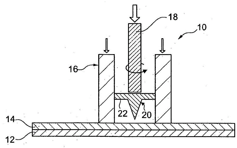
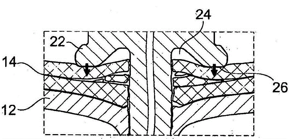
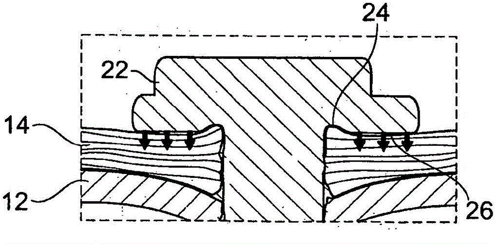
[0019] in figure 1 A joining device 10 is shown in simplified form in, by means of which two (or more) components 12, 14 can be joined by friction element welding. The lower member 12 is made of metal material, and the upper member 14 is made of fiber reinforced plastic.

[0020] The equipment includes a supporting device 16 for fixing the members 12 and 14 and for preventing the members 12 and 14 from lifting up due to the material rising during the welding of the friction element. In addition, the device also includes a driving device 18 that rotates and depresses the friction element 20. For example, torque transmission or force transmission can be implemented by a cutter head acting on the head 22 of the friction element 20. The supporting device 16 is actively adjusted so that the force acting on the members 12, 14 can be adjusted independently of the force exerted on the friction element 20 by the driving device 18.

[0021] Use in figure 1 The joining device 10 shown in FI...


PUM


Abstract

The invention relates to a method and device for joining members. According to the method of the invention, at least one of the members (12, 14) is made of fibre reinforced plastics, and a member complex is joined by friction welding of the members (12, 14) using an initially separate friction element (20), wherein the friction element (20) forms a fixed composition part of the member complex during the welding and friction process. The device according to the invention includes a support device (16) for fixing the members (12, 14) and a drive device (18) for rotating and pressing the friction element (20), wherein the force applied to the member (12, 14) by the support device (16) can be adjusted independent of the force applied to the friction element (20) by the drive device (18).

Description

Technical field [0001] The invention relates to a method for joining components, at least one of which is composed of fiber reinforced plastic. In addition, the present invention also relates to a device for implementing the method. Background technique [0002] It has been proved that a variety of traditional joining methods are not suitable for certain material combinations or are not economical, especially (with the current development trend in automobile manufacturing and other industrial branches) in the following cases: composed of fiber reinforced plastics The components should be connected to other components, usually made of metallic materials. Up to now, components made of fiber-reinforced plastics are often joined by blind riveting or punching riveting. However, blind rivets are associated with the equipment technology used and the components (blind rivets) used, which is a high-cost process. In addition, in order to achieve blind riveting, prefabricated holes must ...

Claims


Application Information

Patent Timeline
Patent Type & Authority Applications(China)
IPC IPC(8): B29C65/06B29C65/34B23K20/12
CPCB23K20/1265B23K20/129B29C65/562B29C65/64B29C65/7841B29C66/1122B29C66/21B29C66/41B29C66/721B29C66/742
Inventor M·威廉A·福斯特J·瓦格纳
Owner BAYERISCHE MOTOREN WERKE AG
Learn More