High-frequency micro-vibration isolation device of spacecraft control moment gyroscope
A technology for controlling torque gyroscopes and isolation devices, which is applied in the directions of aerospace vehicle guidance devices, vibration suppression adjustment, non-rotation vibration suppression, etc. problem, to achieve the effect of good high-frequency vibration isolation, simple configuration, high reliability and stability
Active Publication Date: 2015-10-14
NAT UNIV OF DEFENSE TECH
View PDF6 Cites 19 Cited by
- Summary
- Abstract
- Description
- Claims
- Application Information
AI Technical Summary
Problems solved by technology
[0009] However, the existing micro-vibration isolation devices generally have shortcomings such as complex configuration, low reliabil
Method used
View moreImage
Smart ImageViewing Examples

Examples
 PUM
 Abstract
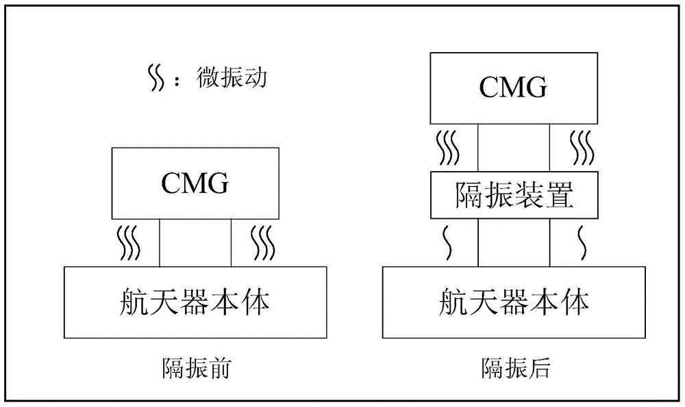
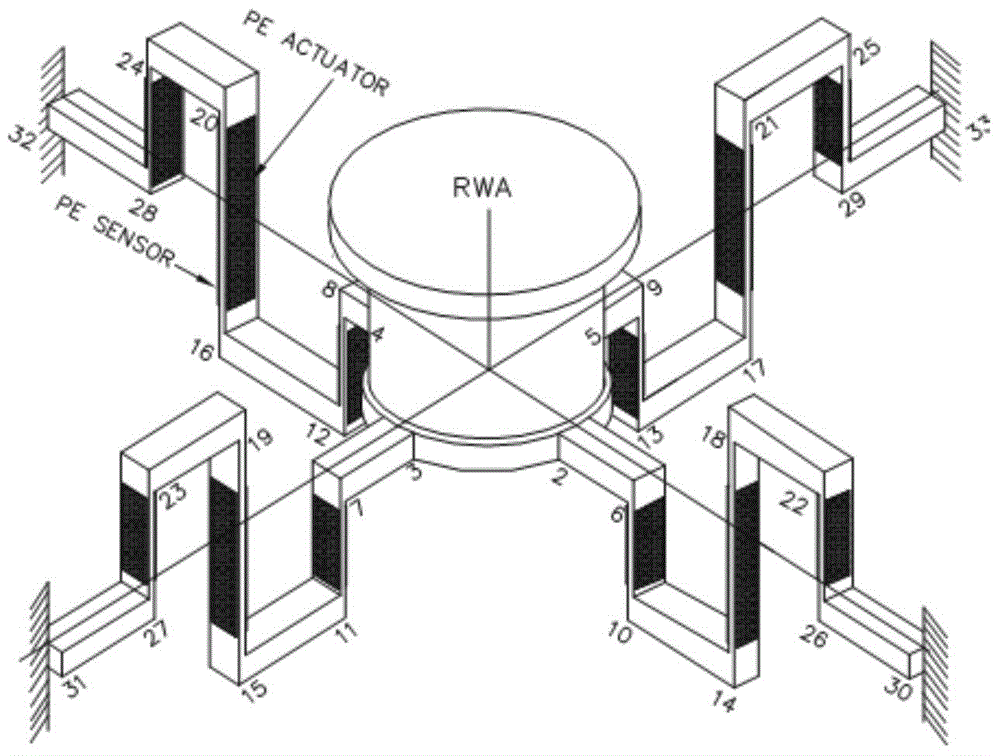
The invention provides a high-frequency micro-vibration isolation device of a spacecraft control moment gyroscope. The high-frequency micro-vibration isolation device is of a central symmetry structure and comprises an installation plate (1), a bottom plate (3) and vibration isolation units arranged between the installation plate (1) and the bottom plate (3). Each vibration isolation unit comprises a radial damping unit (4), an axial damping unit (5) and an elastic supporting unit (6). According to the novel micro-vibration isolation device, vibration isolation performance is good at CMG work rotation speed, six-degree-of-freedom micro vibration transferred to a star body can be effectively reduced, and posture stability and pointing accuracy of the star body can be improved.
Description
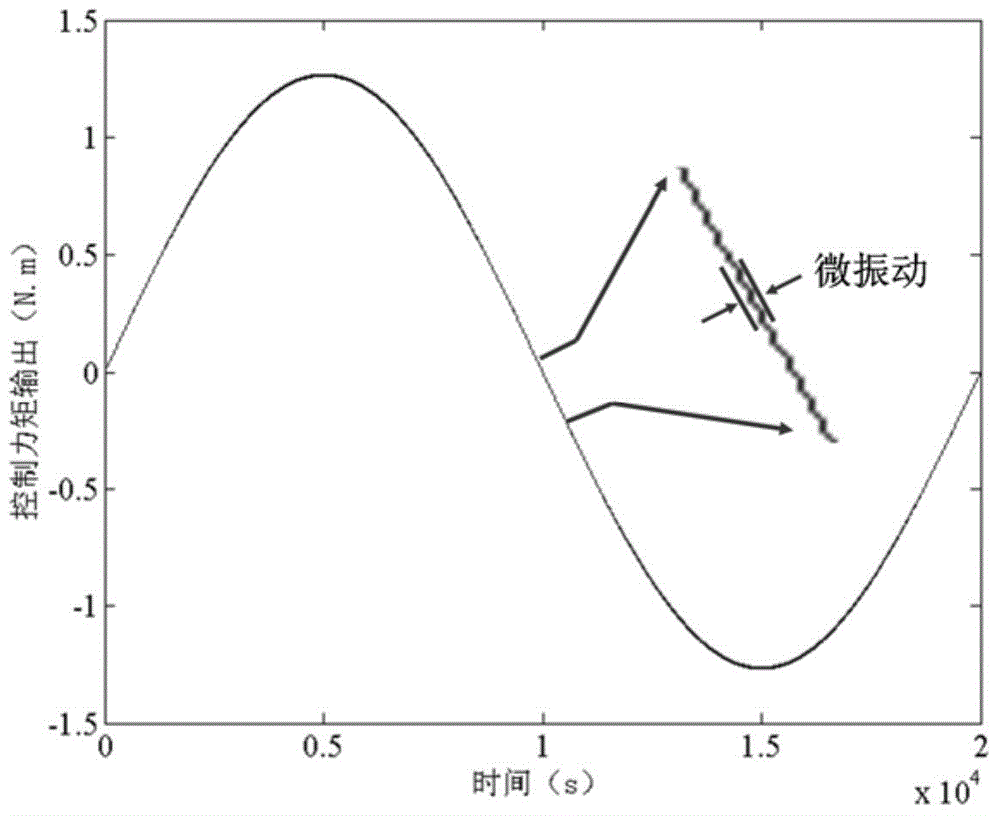
technical field [0001] The invention belongs to the technical field of passive vibration isolation, and in particular relates to a high-frequency micro-vibration isolation device for controlling a moment gyroscope of a spacecraft. Background technique [0002] High-performance spacecraft is an important direction of contemporary aerospace development. It is the core equipment for the implementation of accurate target identification and positioning, efficient and safe transmission of space information, deep space exploration and other space missions. Many fields have urgent application requirements and broad application prospects. [0003] A high-performance spacecraft platform needs to have very high pointing accuracy and stability, and a small deviation may have a serious impact on a high-performance spacecraft. For example, for an earth observation satellite at an orbital altitude of 500km, the angular vibration of 2.06arcsec causes the field of view to deviate up to 50m....
Claims
Login to View More Application Information
Patent Timeline
 IPC IPC(8): B64G1/28F16F15/023F16F15/04
Inventor 李东旭石声浩蒋建平罗青魏展基
Owner NAT UNIV OF DEFENSE TECH