Multipurpose belt deviation correcting device

A correction device and multi-purpose technology, applied in the direction of transportation and packaging, conveyor objects, conveyors, etc., can solve the problems of inability to realize real-time control of the positive belt, loose structure of the deviation correction device, and poor working environment of the conveyor belt, etc., to achieve Compact structure, improved service life and high adjustment efficiency

Inactive Publication Date: 2015-10-14
阮敬刚
View PDF1 Cites 1 Cited by
  • Summary
  • Abstract
  • Description
  • Claims
  • Application Information

AI Technical Summary

Problems solved by technology

[0005] The above-mentioned patents have the following defects in the long-term use process: 1. The working environment of some conveyor belts is harsh; Therefore, the deviation adjustment function cannot be realized; therefore, the deviation adjustment and correction device needs to be cleaned frequently, which is inconvenient to use
[0007] 3. Since the belt is always in contact with the deflection adjustment roller, the angle of the deflection adjustment roller needs to be more precise. If there is an angle deviation, it will not only fail to achieve the effect of deflection adjustment, but will have a reverse effect
[0008] 4. The structure of the deviation adjustment and correction device is loose, usually in a horizontal layout, and requires a large installation area. Therefore, it can only be used under the return belt of the transmission belt. It has a single function and cannot realize real-time control of the forward belt.

Method used


Image

  • Multipurpose belt deviation correcting device
  • Multipurpose belt deviation correcting device
  • Multipurpose belt deviation correcting device

Examples


Embodiment Construction

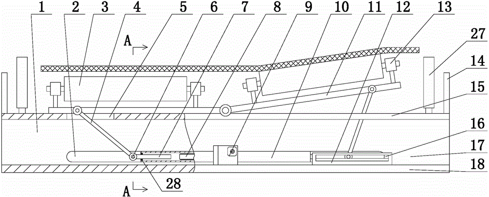
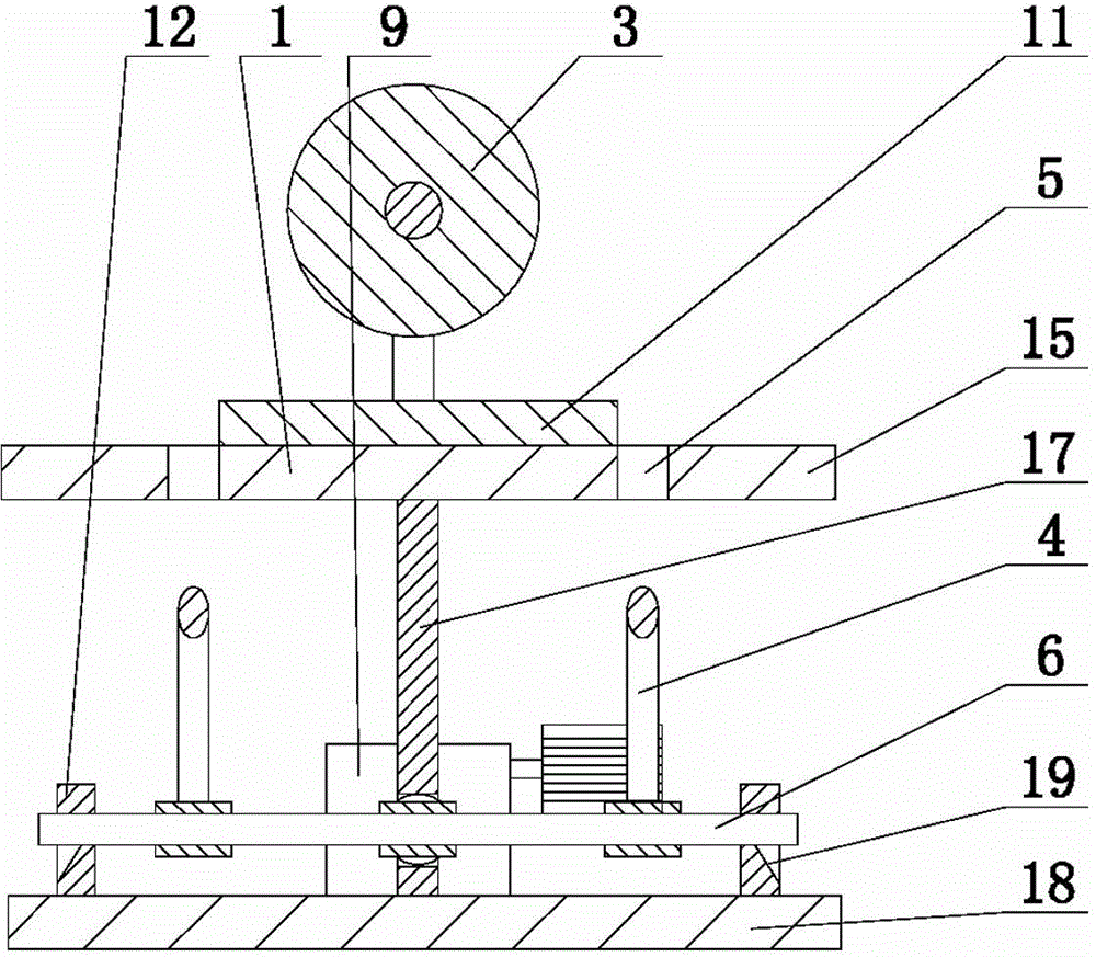
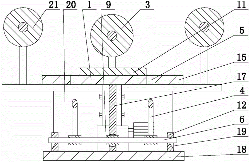
[0029] The present invention includes a frame 1, which is characterized in that: both sides of the upper surface of the frame 1 are provided with overturning frames 11, and both overturning frames 11 are provided with deflection adjustment rollers 3 through bearings 13, and the opposite ends of the two overturning frames 11 are on the same machine The frame 1 is hinged; the bottom of the flip frame 11 is hingedly provided with a pole 4; the frame 1 is provided with a lead screw reducer 9, and the two sides of the lead screw reducer 9 are screw rods 8, and the two parts in the frame 1 Both ends are provided with slideway groups 12, and both slideway groups 12 are provided with slide rods 6, and the two slide rods 6 are respectively provided with ejector rods 7 corresponding to the screw rods 8 on both sides of the screw reducer 9; The poles 4 at the bottom of the two overturning frames 11 are hinged with the two slide bars 6 respectively.

[0030] As a preferred solution of the...


PUM


Abstract

The invention discloses a multipurpose belt deviation correcting device, and relates to improvement on the structure of a belt deviation correcting device. The invention provides the belt deviation correcting device which is compact in structure and multipurpose. The multipurpose belt deviation correcting device comprises a rack. The multipurpose belt deviation correcting device is characterized in that turnover frames are arranged at two sides of the upper surface of the rack, wherein deviation regulating rollers are arranged on the two turnover frames by bearings; opposite ends of the two turnover frames are hinged to the rack; supporting rods are hinged to the bottoms of the turnover frames; a lead screw speed reducer is arranged in the rack; lead screws are arranged at the two sides of the lead screw speed reducer; slide path sets are arranged at the two ends in the rack; slide rods are arranged in the two slide path sets; ejector rods, which are corresponding to the lead screws at the two sides of the lead screw speed reducer, are respectively disposed on the two slide rods, on the two slide rods; and the supporting rods on the bottoms of the two turnover frames are hinged to the two slide rods respectively.

Description

technical field [0001] The invention relates to an improvement of the structure of a belt deviation correcting device, in particular to a multipurpose belt deviation correcting device. Background technique [0002] Belt deviation is the most common fault during the operation of belt conveyors. In the actual operation process, belt deviation not only causes great damage to the belt conveyor itself, but also poses safety hazards, affects production efficiency, transports goods quality, and pollutes the environment. . [0003] The existing belt correction and correction technology mostly adopts methods such as setting a conical roller at the edge of the drive roller, and applying a lateral thrust from the side of the belt for correction. Longitudinal folding, tearing and other problems will affect the life of the belt and increase the operating cost. [0004] The patent number is 200620089505.0, and the name is the invention patent of "A Belt Deviation Correcting Device". The...

Claims


Application Information

Patent Timeline
Patent Type & Authority Applications(China)
IPC IPC(8): B65G15/64B65G39/16B65G23/44
CPCB65G39/16B65G23/44
Inventor 阮敬刚
Owner 阮敬刚
Why Eureka
Try Eureka