Chain Tensioner
A technology of chain tensioning device and tensioning device, which is applied in the direction of transmission device, belt/chain/gear, mechanical equipment, etc., can solve the problems of controlling pressing force, difficult to realize, not considering adjustment of oil pressure, etc. simple structure
- Summary
- Abstract
- Description
- Claims
- Application Information
AI Technical Summary
Problems solved by technology
Method used
Image
Examples
Embodiment 1
[0058] The chain tensioner 100 according to the first embodiment of the present invention will be described with reference to the drawings.
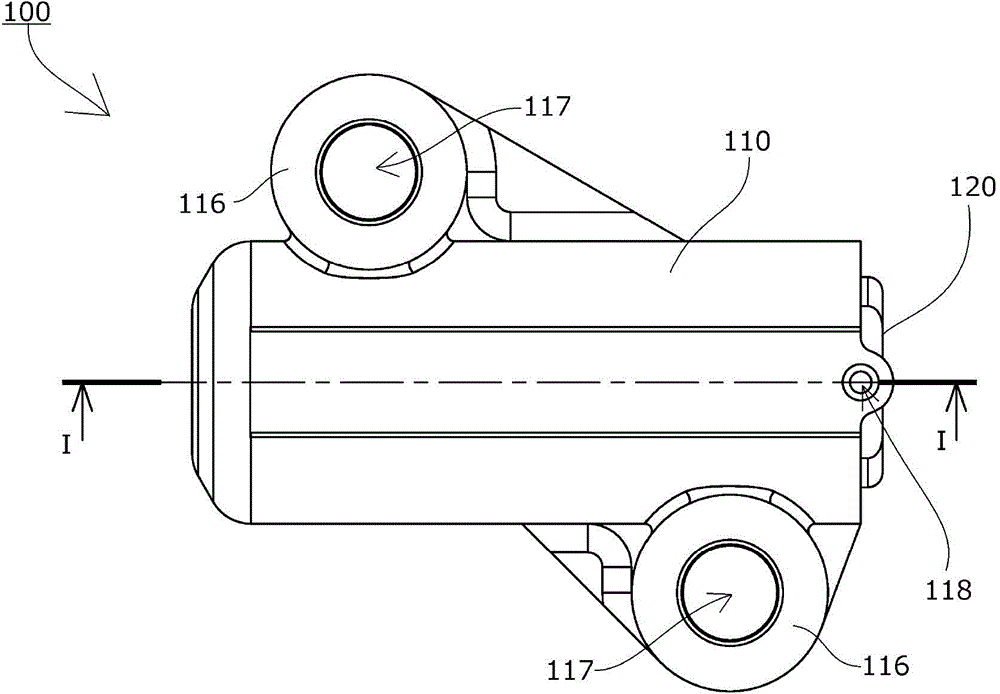
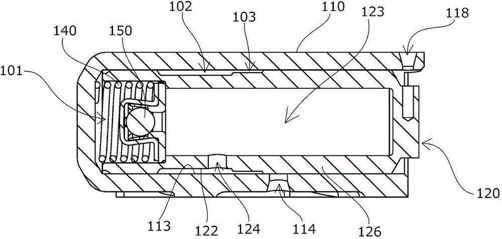
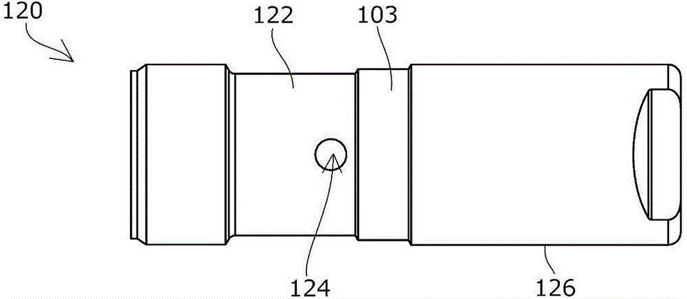
[0059] Such as Figure 1 to Figure 3 As shown, the chain tensioner 100 according to the first embodiment of the present invention includes: a tensioner main body 110 having a cylindrical plunger receiving hole with one side open; and a cylindrical plunger 120 slidably inserted into the in the plunger housing hole; and a coil spring 140 which is retractably accommodated in the pressure oil chamber 101 formed between the plunger housing hole and the rear end side of the plunger 120 and urges the plunger 120 in the protruding direction. afterburner unit.
[0060] The chain tensioner 100 according to this embodiment is a member fixed in an engine having a chain guide mechanism, and therefore, as figure 1 As shown, the tensioner body 110 has a mounting portion 116 having a mounting hole 117 through which a bolt or the like passes.
[0061...
Embodiment 2
[0104] The chain tensioner 200 according to the second embodiment of the present invention is as follows: Figure 14 , Figure 15 As shown, a cylindrical oil supply space 202 is formed between the main body groove portion 219 and the outer periphery of the plunger body 226. In this point, it is different from the chain tensioner 100 according to the first embodiment described above. The inner circumference 213 of the receiving hole forms the main body groove 219 by a main body annular recess with a larger diameter than the inner circumference 213 of the plunger receiving hole, and the other structures are the same (the symbols of the same members and structures are the hundreds digit is 2 , the last two digits are the same as those in the first embodiment).
[0105] The operation of the chain tensioner 200 according to this embodiment is the same as that of the chain tensioner 100 according to the above-mentioned first embodiment, and produces the same effect.
[0106] Furth...
Embodiment 3
[0112] The chain tensioner 300 according to the third embodiment of the present invention is as follows: Figure 17 As shown, compared with the first modified example of the chain tensioner 100 according to the first embodiment described above, two oil supply holes 314 with a smaller flow rate are provided at intervals in the protruding direction of the plunger 320 . , other structures are the same (the symbol of the same member and structure is a symbol with a hundred digit of 3, and the last two digits are the same as those of the first embodiment).
[0113] In the chain tensioner 300 according to this embodiment, the oil supplied from one oil supply hole 314a is set so that the plunger groove 322 faces only one oil supply hole 314a in the normal rotation range. The flow rate is reduced and supplied to the oil supply space 302 .
[0114] In the high-speed rotation region, by setting the plunger groove portion 322 to face the two oil supply holes 314a, b, a large amount of o...
PUM
 Abstract
Description
Claims
Application Information
 - R&D
- Intellectual Property
- Life Sciences
- Materials
- Tech Scout
- Unparalleled Data Quality
- Higher Quality Content
- 60% Fewer Hallucinations
Browse by: Latest US Patents, China's latest patents, Technical Efficacy Thesaurus, Application Domain, Technology Topic, Popular Technical Reports.
© 2025 PatSnap. All rights reserved.Legal|Privacy policy|Modern Slavery Act Transparency Statement|Sitemap|About US| Contact US: help@patsnap.com


