Complete dynamic balance type coupling
A coupling and semi-coupling technology, which is applied in the field of high-performance connection transmission of rotating units, can solve problems affecting the accuracy of dynamic balance, achieve the effects of improving dynamic balance accuracy, improving coaxiality, and eliminating geometric unbalance factors
- Summary
- Abstract
- Description
- Claims
- Application Information
AI Technical Summary
Problems solved by technology
Method used
Image

Examples
Embodiment
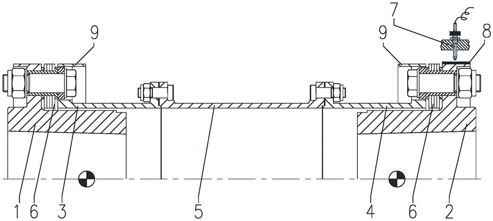
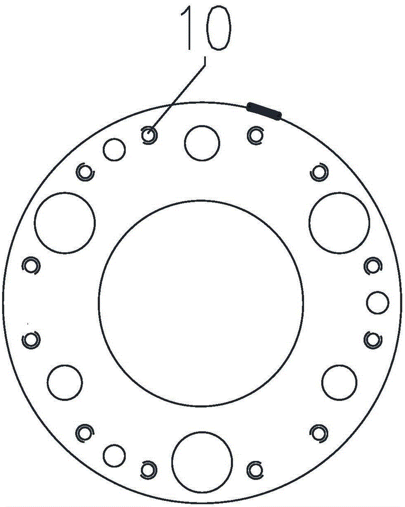
[0022] Such as figure 1 and figure 2 Shown: complete dynamic balance coupling, including power input half coupling 1, power output half coupling 2, input end sheath 3, output end sheath 4, intermediate section 5, diaphragm group 6, Infrared probe 7, key phase magnetic strip 8 and counterweight flange 9. The input end sheath 3 and the output end sheath 4 are set on the shaft hubs of the power input half coupling 1 and the power output half coupling 2 through the counterweight flange 9 respectively, and the power input half coupling The flanges of the coupling 1 and half coupling 2 at the power output end are close to their outer ends, which makes the quality of the coupling close to the supports (bearings) of the machines on both sides to the maximum extent, which is beneficial to improve the shock absorption capacity of the unit. The input sheath 3 is connected to the output sheath 4 through the intermediate section 5 . The diaphragm group 6 is arranged between the input e...
PUM
 Abstract
Description
Claims
Application Information
 - Generate Ideas
- Intellectual Property
- Life Sciences
- Materials
- Tech Scout
- Unparalleled Data Quality
- Higher Quality Content
- 60% Fewer Hallucinations
Browse by: Latest US Patents, China's latest patents, Technical Efficacy Thesaurus, Application Domain, Technology Topic, Popular Technical Reports.
© 2025 PatSnap. All rights reserved.Legal|Privacy policy|Modern Slavery Act Transparency Statement|Sitemap|About US| Contact US: help@patsnap.com