Slip ring arrangement

A technology of slip ring and ring, applied in the field of slip ring arrangement

Inactive Publication Date: 2015-10-14
ABB TECH AG
View PDF8 Cites 2 Cited by
  • Summary
  • Abstract
  • Description
  • Claims
  • Application Information

AI Technical Summary

Problems solved by technology

[0006] One problem with prior art slip ring arrangements used in boats to transfer current to the electric motor in the compartment is the height of the arrangement

Method used


Image

  • Slip ring arrangement
  • Slip ring arrangement
  • Slip ring arrangement

Examples


Embodiment Construction

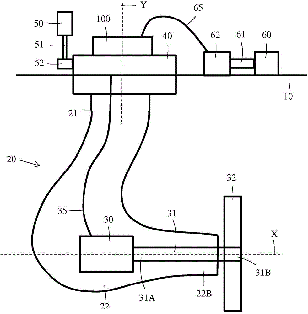
[0030] figure 1 A vertical section is shown of a compartment arrangement in a ship to which the slip ring arrangement according to the invention can be applied. The compartment arrangement comprises a hollow compartment 20 having an upper part 21 and a lower part 22 . The compartment 20 is attached at the hull 10 of the ship from the upper part 21 . The lower part 22 of the compartment 20 forms a longitudinal compartment comprising a first electric motor 30 and a first shaft 31 . A first end 31A of the first shaft 31 is connected to the electric motor 30 and a second end 31B of the first shaft 31 protrudes from the rear end 22B of the lower part 22 of the compartment 20 . The pusher 32 is connected to the second outer end 31B of the first shaft 31 . The axis X of the first shaft 31 forms a shaft line. The compartment 20 is rotatably attached to the vessel 10 via the upper part 21 so that the compartment 20 can be turned 360 degrees around a vertical central axis Y. The up...


PUM


Abstract

Slip ring arrangement (100) for transferring electric power between a stationary part (10) and a rotatable part (20) comprises annular slip rings (101. 102, 103) positioned coaxially around a centre axis (Y) at a radial distance from each other and having at least one contact surface (S1, S2). First power supply conductors (111, 112, 113) are fixedly attached to the at least one contact surface (S1, S2) of the slip rings (101, 102, 103). Sliding contact means (131, 132, 133) are in sliding contact with the at least one contact surface (S1, S2) of the slip rings (101, 102, 103). Second power supply conductors (121, 122, 123) are fixedly attached to the sliding contact means (121, 122, 123). Said sliding contact means (131, 132, 133) are stationary and said slip rings (101, 102, 103) rotate with the rotating part (20) or vice a versa.

Description

technical field [0001] The invention relates to a slip ring arrangement according to the preamble of claim 1 . Background technique [0002] DE 4406042 discloses an electrical connection for a rotatable spotlight. The arrangement includes a first pair of concentric conductive pillars, the first pair of concentric conductive bodies overlying a second pair of concentric conductive pillars. The first pair of cylinders and the second pair of cylinders have a common axis of rotation, and the diameter of the cylinders of the first pair of cylinders corresponds to the diameter of the corresponding cylinders of the second pair of cylinders. Each post of the first pair of posts includes a contact spring extending downwardly and in contact with an inner surface of a corresponding post of the second pair of posts. The first pair of cylinders is fixed while the second pair of cylinders rotates. A bar is provided at the axis of rotation and passes through the arrangement. The incmoin...

Claims


Application Information

Patent Timeline
Patent Type & Authority Applications(China)
IPC IPC(8): H01R39/64
CPCH01R39/64
Inventor 泰穆·耶赫科宁
Owner ABB TECH AG
Why Eureka
Try Eureka