Hydraulic excavator movable arm potential energy recovery system

A technology of potential energy recovery and motorized arms, which is applied in the direction of earth movers/shovels, construction, etc., can solve the problems of potential energy waste, achieve energy saving, reduce energy consumption, and highlight the effect of substantive features

Pending Publication Date: 2015-10-21
SHANDONG LISHIDE MACHINERY
View PDF0 Cites 9 Cited by
  • Summary
  • Abstract
  • Description
  • Claims
  • Application Information

AI Technical Summary

Problems solved by technology

[0002] The hydraulic excavator is a kind of widely used construction machinery. The weight of the working device accounts for about 1/4 of the weight of the whole machine. During the oper

Method used


Image

  • Hydraulic excavator movable arm potential energy recovery system

Examples


Embodiment Construction

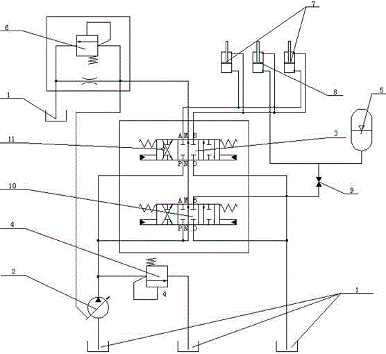
[0018] In order to clearly illustrate the technical features of the solution, the solution will be described below through a specific implementation mode combined with the accompanying drawings.

[0019] It can be seen from the drawings that a hydraulic excavator boom potential energy recovery system includes a fuel tank 1 and a hydraulic pump 2, and also includes two main control cylinders 7 and an auxiliary cylinder 8 for driving the movement of the boom. Oil cylinders 8 are arranged in parallel with two main control oil cylinders 7 respectively. The cylinder rods of the two main control oil cylinders 7 and the auxiliary oil cylinder 8 move synchronously to jointly control the rise or fall of the boom. The main control oil cylinder 7 is a conventional The hydraulic cylinder, the auxiliary cylinder 8 has the function of energy recovery, and the auxiliary cylinder 8 is located between the two main control cylinders 7 . The hydraulic pump 2 communicates with the rod cavity and ...


PUM


Abstract

The invention provides the technical scheme of a hydraulic excavator movable arm potential energy recovery system. The scheme also comprises two main control oil cylinders and an auxiliary oil cylinder which are used for driving a movable arm to move, wherein the auxiliary oil cylinder is arranged in parallel with the two main control oil cylinders; cylinder rods of the two main control oil cylinders and a cylinder rod of the auxiliary oil cylinder synchronously move; a hydraulic pump is communicated with rod cavities and rodless cavities of the two main control oil cylinders and a rod cavity of the auxiliary oil cylinder by a second reversing valve; and a rodless cavity of the auxiliary oil cylinder is communicated with an energy accumulator. According to the invention, the potential energy produced when the auxiliary oil cylinder descends can be recovered in the energy accumulator; the energy accumulator releases the stored potential energy when the movable arm ascends; and compared with the prior art, the whole hydraulic system has the advantages that the energy consumption is greatly reduced; heating is reduced; and the reutilization of energy is realized.

Description

technical field [0001] The invention relates to the field of engineering machinery hydraulic transmission, in particular to a potential energy recovery system for hydraulic excavator arms. Background technique [0002] The hydraulic excavator is a kind of widely used construction machinery. The weight of the working device accounts for about 1 / 4 of the weight of the whole machine. During the operation of the excavator, the working device must be lifted and lowered once in each operation cycle. When lifting, a large amount of The energy, the potential energy when falling is wasted again. In the prior art, this is the weak point that the prior art exists. Contents of the invention [0003] The technical problem to be solved by the present invention is to provide a technical solution for the potential energy recovery system of the arm of the hydraulic excavator in view of the deficiencies in the prior art. Using the present invention, the potential energy of the working devi...

Claims


Application Information

Patent Timeline
IPC IPC(8): E02F9/22
Inventor 李兆良李永刚张景颜刘军郭立金许跃雷张建秦小兵马建宁
Owner SHANDONG LISHIDE MACHINERY
Why Eureka
Try Eureka