A device interface connection structure for OLED production inline system

A connection structure and equipment connection technology, applied in the direction of mechanical equipment, fixtures, etc., can solve problems such as processing deviation, difficulty in ensuring air tightness, and uneven processing capabilities of equipment, so as to ensure airtightness, improve feasibility, and facilitate plant planning Effect

Active Publication Date: 2017-03-08
HEFEI XINSHENG OPTOELECTRONICS TECH CO LTD +1
View PDF6 Cites 0 Cited by
  • Summary
  • Abstract
  • Description
  • Claims
  • Application Information

AI Technical Summary

Problems solved by technology

[0003] Due to the different production capabilities of different equipment manufacturers, the processing capabilities of the equipment vary, and there are often problems that the deviation between the drawing and the actual processing exceeds a reasonable range, such as the deviation of the center line, insufficient connection interface, etc., resulting in the failure of the equipment to be assembled.
Especially for OLED Inline equipment, according to the process sequence and the requirements of maximizing the use of factory buildings, there will be equipment placed incorrectly, which provides greater difficulties for processing and equipment assembly
[0004] At present, the main ways of connecting equipment are: the equipment is directly connected through the downstream connector, that is, the connector is directly connected to the upstream equipment with screws; Only the distance can be adjusted, and the airtightness is difficult to guarantee

Method used


Image

  • A device interface connection structure for OLED production inline system
  • A device interface connection structure for OLED production inline system
  • A device interface connection structure for OLED production inline system

Examples


Embodiment Construction

[0026] In order to make the purpose, technical solutions and advantages of the embodiments of the present invention clearer, the technical solutions in the embodiments of the present invention will be clearly and completely described below in conjunction with the drawings in the embodiments of the present invention. Obviously, the described embodiments It is a part of embodiments of the present invention, but not all embodiments. Based on the embodiments of the present invention, all other embodiments obtained by persons of ordinary skill in the art without making creative efforts belong to the protection scope of the present invention.

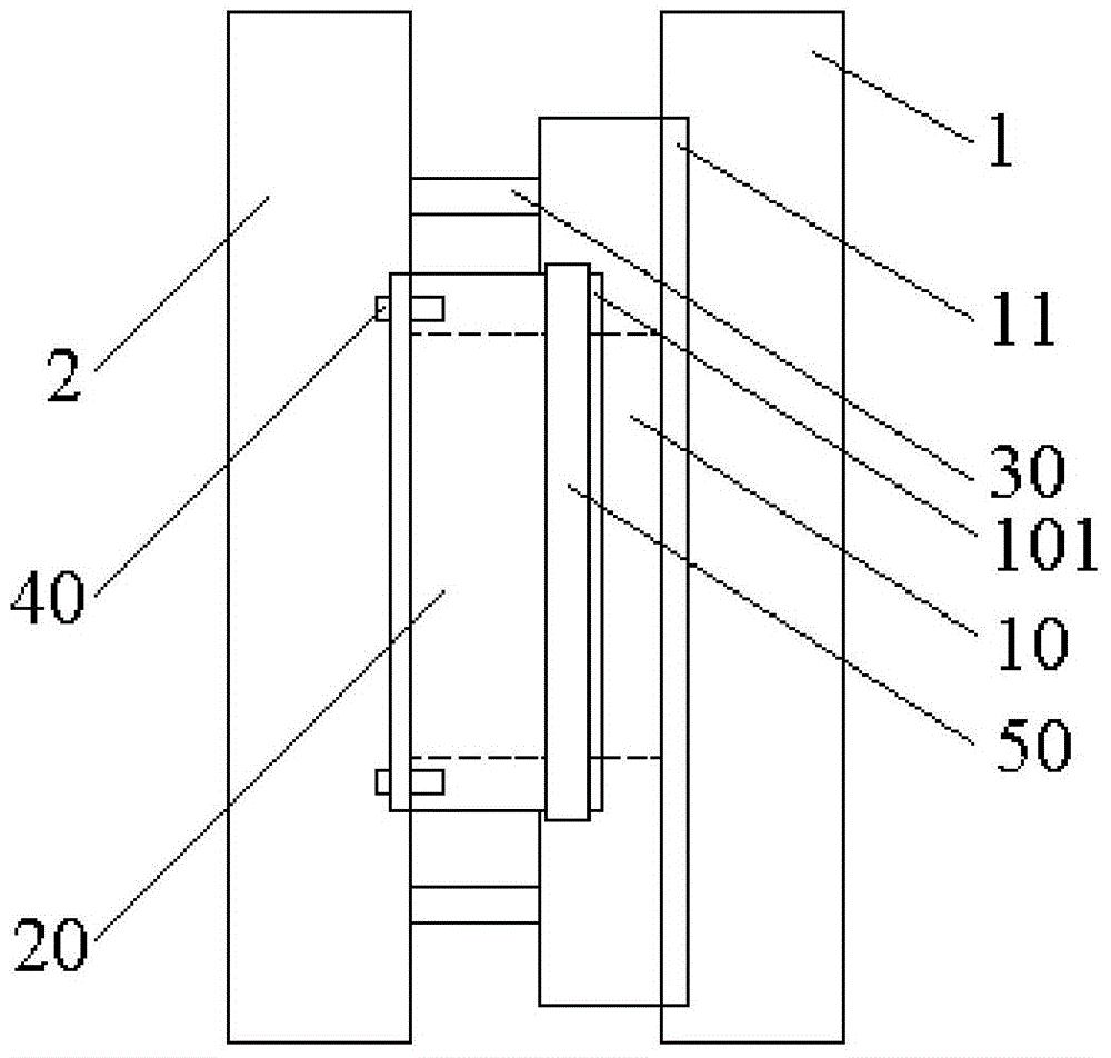
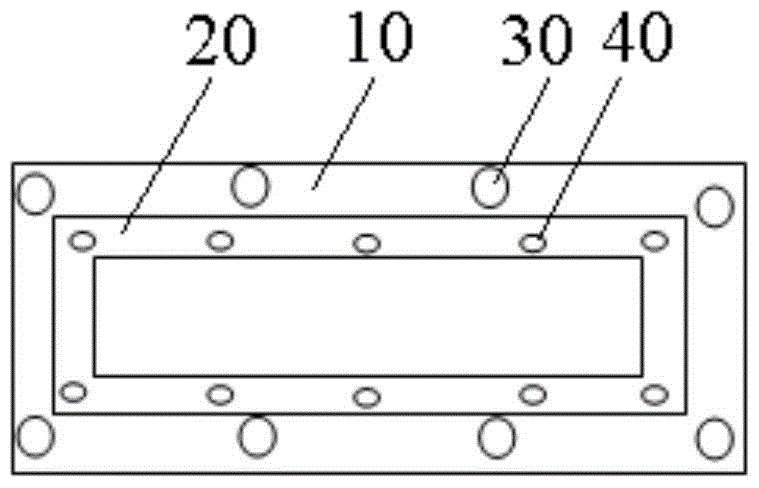
[0027] Such as figure 1 and 2 As shown, the device interface connection structure for OLED production inline system provided by the embodiment of the present invention is set between the first device 1 and the second device 2. In this embodiment, the first device is an upstream device. The second device 2 is a downstream device, but it is n...


PUM


Abstract

The invention relates to the technical field of equipment planning and mounting, and discloses an equipment interface connecting structure which is arranged between first equipment and second equipment. The equipment interface connecting structure comprises an outer connector with an inner channel, and an outer connector, wherein one end of the outer connector is connected with the first equipment; an inner cavity is formed in the other end of the outer connector in a sleeving mode; one end of the inner connector is connected with the second equipment, and the other end of the inner connector is arranged in the sleeved inner cavity in the sleeving mode; a plurality of air cylinders capable of stretching out and drawing back under the control of a plurality of controllers are arranged on the end surface at one end at which the outer connector and the inner connector are connected; and piston rods of the air cylinders are resisted against the second equipment. According to the equipment interface connecting structure, the inner connector and the outer connector can relatively move under the driving of the air cylinders, and a connecting distance can be properly regulated, so that the equipment connection is adjustable in length; and by regulating expansion amount of different air cylinders, angles of the inner and the outer connectors can be regulated within certain angle, so that the problem that the equipment cannot be set up due to processing deviations is solved, and therefore, the equipment interface connecting structure is especially suitable for equipment connection with certain angle.

Description

technical field [0001] The invention relates to the technical field of equipment planning and installation, in particular to an equipment interface connection structure for an OLED production inline system. Background technique [0002] Organic electroluminescent devices (OLEDs) have the characteristics of low power consumption, light weight, high brightness, wide field of view, high contrast and fast response. Scholars at home and abroad have conducted many researches on them and achieved many results. At present, the industrialization of OLED is gradually accelerating, and production lines of different sizes have been built one after another. OLED is determined by its own material characteristics, requiring the electroluminescent layer to work in a vacuum or an oxygen-free environment before packaging. Equipment construction belongs to Inline. system, the equipment is connected end to end. This structure has high requirements for the rationality of the layout and the proce...

Claims


Application Information

Patent Timeline
Patent Type & Authority Patents(China)
IPC IPC(8): F16B1/02
CPCF16B1/02
Inventor 全威张家豪刘晴
Owner HEFEI XINSHENG OPTOELECTRONICS TECH CO LTD
Why Eureka
Try Eureka