External pressing type flexible duct valve

A flexible pipeline and external pressure technology, applied in the field of pipeline valves, can solve problems such as high driving power and fluid pollution, achieve the effects of reducing manufacturing precision requirements, improving hygiene and safety quality, and simple structure

Active Publication Date: 2015-10-21
楚天源创生物技术(长沙)有限公司
View PDF4 Cites 16 Cited by
  • Summary
  • Abstract
  • Description
  • Claims
  • Application Information

AI Technical Summary

Problems solved by technology

However, since the fluid flows through the valve body during the delivery process, it will be in contact with the valve core and other components of the valve, and these movable components will cause a certain degree of pollution to the fluid due to friction, damage, etc. after a certain period of use.
In addition, the spool of the traditional valve, whether it is the spool of the ball valve or the disc of the butterfly valve, requires a large torque during the opening or closing process, so the required driving power is large

Method used


Image

  • External pressing type flexible duct valve
  • External pressing type flexible duct valve
  • External pressing type flexible duct valve

Examples


Embodiment 1

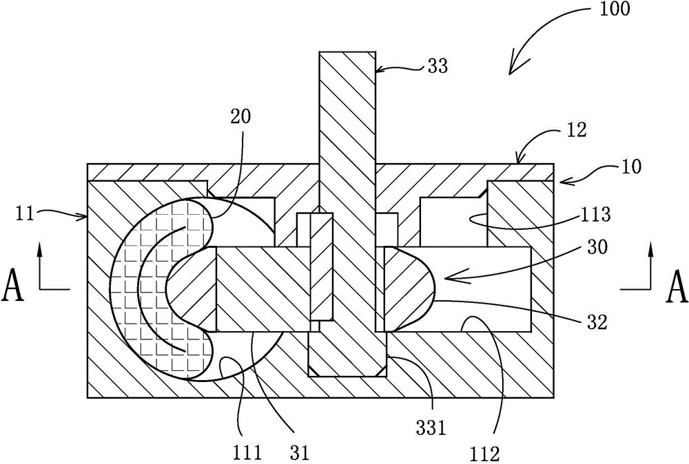
[0026] The external pressure flexible pipeline valve 100 of the present invention includes a valve body 10 , a flexible pipeline 20 passing through the valve body 10 and a rotating pressure applying component 30 disposed in the valve body 10 .

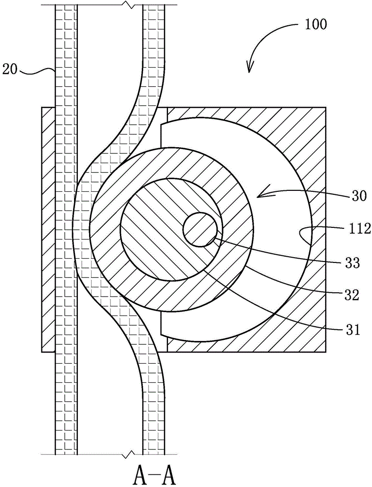
[0027] like Figure 5A ~ Figure 5C As shown, the valve body 10 includes a main body 11 and an end cover 12, the main body 11 is a rectangular block, and a cavity 112 is provided in the middle of the main body 11, as Figure 5B , the cavity 112 is a cylindrical cavity, the diameter and height of which are slightly larger than the diameter and height of the pressure roller 32 of the rotating pressure applying assembly, so that the pressure roller 32 can rotate freely therein. One side of the cavity is provided with a through hole 111, the through hole 111 communicates with the cavity 112, and the center line of the through hole 111 is perpendicular to the horizontal center line of the cavity 112, and the through hole 111 is used for pass...

Embodiment 2

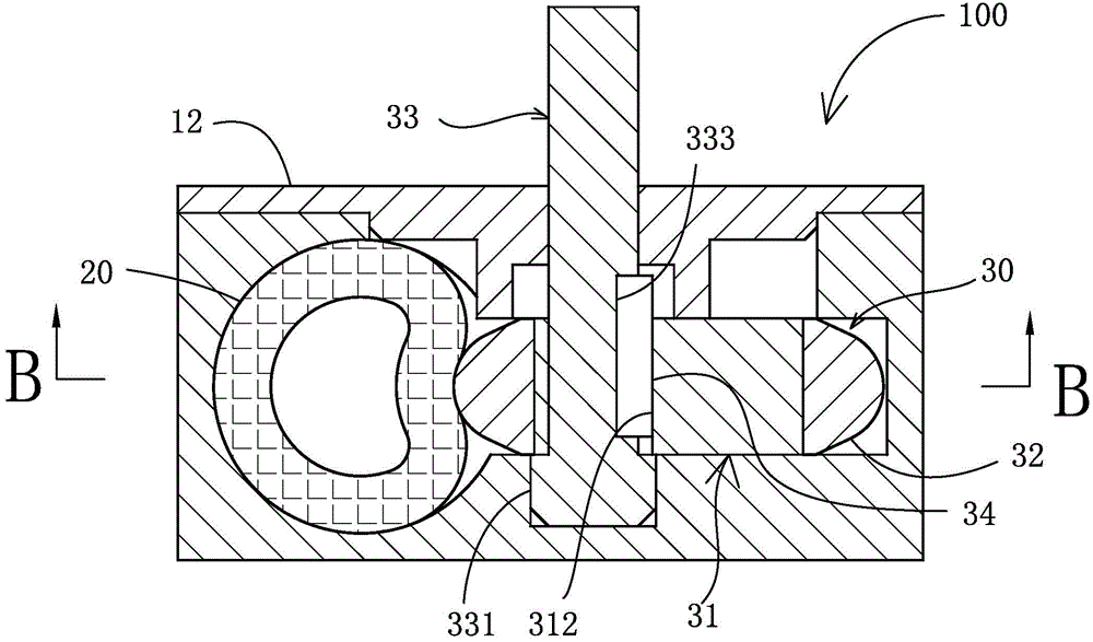
[0031] In this embodiment, the basic structure of the external pressure flexible pipe valve 100 is the same as that of Embodiment 1, the difference is that two sets of flexible pipes 20 and two sets of rotating pressure applying components 30 are arranged in the valve body 10 to form two sets of linkages. structure.

[0032] like Figure 8A ~ Figure 8C and Figure 9 As shown, the valve body 10 is axially provided with two through-holes 111 for piercing flexible pipes and a cylindrical cavity 112 for accommodating rotating pressure-applying components. Each of the two through-holes 111 A flexible pipe 20 for transporting liquid is pierced, and a rotating pressure applying assembly 30 is respectively arranged in the two cavities 112. 30 can be rotated with a phase difference of 180 degrees under manpower or electric drive, respectively crushing or loosening the flexible pipe, thereby closing and opening the liquid channel.

[0033] like Figure 9 As shown, the valve body 10 ...


PUM


Abstract

Disclosed is an external pressing type flexible duct valve. The flexible duct valve is provided with a valve body. The valve body is provided with a through hole allowing a flexible duct to penetrate through and a cylindrical cavity for accommodating a rotary pressing component. The flexible duct used for delivering liquid penetrates through the through hole. The rotary pressing component is arranged in the cavity and comprises an eccentric wheel, a pressing wheel, a wheel axle and a key. The rotary pressing component can be driven manually or electrically to rotate so as to press or release the flexible duct, so that a liquid channel is closed and opened. Due to the fact that the rotary pressing component of the flexible duct valve is completely isolated from fluid in the flexible duct, pollution can not be caused to fluid flowing through the duct valve, and power required for opening or closing the duct valve is small. The external pressing type flexible duct valve is simple in structure and easy to implement.

Description

【Technical field】 [0001] The invention relates to a pipeline valve, in particular to an external pressure flexible pipeline valve. 【Background technique】 [0002] The valve is a control component in the fluid delivery system, which has functions such as cut-off, adjustment, flow diversion, reverse flow prevention, pressure stabilization, flow diversion or overflow pressure relief. The structure and function of traditional valves, such as ball valves and butterfly valves, are well known. No matter what kind of valve it is, the opening or closing of traditional valves depends on the separation or closure of the spherical surface or disc and the sealing surface. During this process, fluid flows through the valve or is blocked. In the food, pharmaceutical and other industries, there are high requirements for the hygiene and safety of valves, so as to avoid the contamination of liquids when passing through the valves. However, since the fluid flows through the valve body durin...

Claims


Application Information

Patent Timeline
Patent Type & Authority Applications(China)
IPC IPC(8): F16K7/06F16K27/02F16K31/52
CPCF16K7/06F16K27/0236F16K31/52
Inventor 肖立峰
Owner 楚天源创生物技术(长沙)有限公司
Why Eureka
Try Eureka