Eureka AIR delivers breakthrough ideas for toughest innovation challenges, trusted by R&D personnel around the world.

Touch clock LED table lamp

A technology for LED desk lamps and clocks, which is applied in the cooling/heating devices of lighting devices, lighting and heating equipment, point light sources, etc., can solve the problems of affecting the service life of LED lamps, shortening the service life of LED lamps, and easy aging of circuits. To achieve the effect of increasing heat dissipation, simple structure and avoiding lines

Inactive Publication Date: 2015-10-21
施婷婷
View PDF5 Cites 7 Cited by
  • Summary
  • Abstract
  • Description
  • Claims
  • Application Information

AI Technical Summary

Problems solved by technology

The adjustment of the position of the lamp head of the table lamp is mostly adjustable up and down, but touch control, left and right position adjustment, and integrated clock functions are rarely used; and with the development of technology, LED lights gradually replace energy-saving lamps, but because the same light source LED The number of lamps is large, so the heat generated will be more, which will affect the service life of the LED lamps, and most of the desk lamps in the prior art adjust the light intensity per unit area by adjusting the voltage. This electronic adjustment method is to a certain extent It also shortens the service life of LED lights. In the prior art, there are also mechanical dimming methods, but this method has many and complicated circuits. After a long time of use, the circuits are prone to aging, and there are potential safety hazards.

Method used


Image

  • Touch clock LED table lamp
  • Touch clock LED table lamp
  • Touch clock LED table lamp

Examples


Embodiment Construction

[0016] The technical solution of this patent will be further described in detail below in conjunction with specific embodiments.

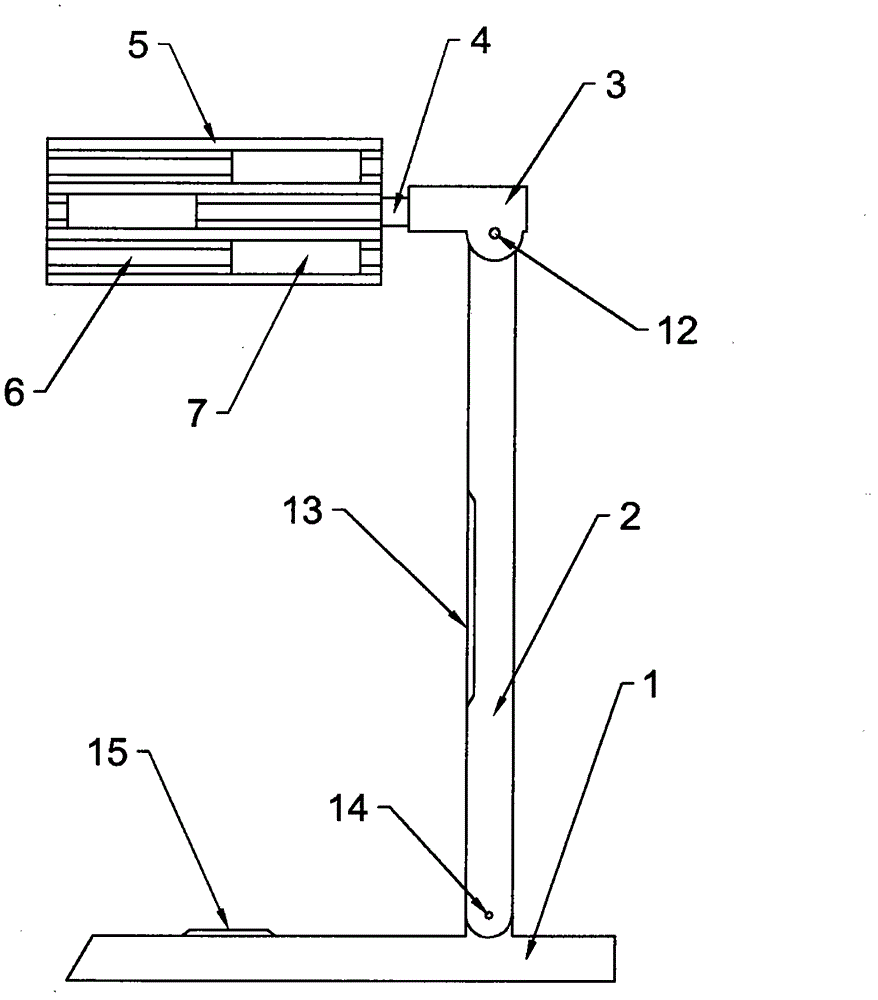
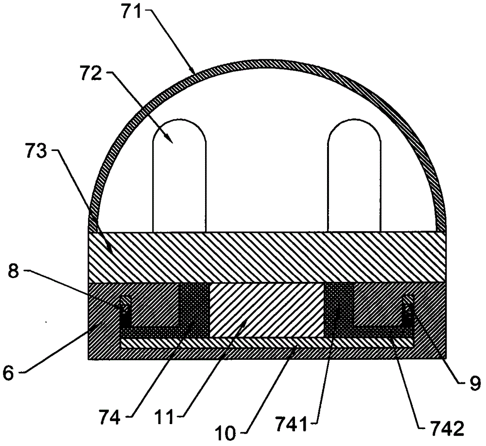
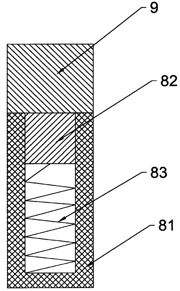
[0017] see Figure 1-4 , a touch clock LED desk lamp, comprising a lamp holder 1, the lamp holder 1 is connected to a lamp post 2 through a lamp holder rotating shaft 14, the lamp post 2 is connected to a lamp housing bracket 3 through a lamp rod rotating shaft 12, and the lamp housing bracket 3 is connected through a bracket rotating shaft 4 The lamp housing 5, the lamp holder 1, the lamp pole 2, the lamp housing bracket 3 bracket and the lamp housing 5 are sequentially connected from bottom to top. The side of the lamp housing 5 is vertically provided with a chute 6, and a luminous Component 7, the chute 6 is provided with a power connection block 9, the light emitting component 7 is electrically connected to the power connection block 9 through the connection component 8 fixed on the light emitting component 7; the lamp holder 1 is also provided...


PUM


Abstract

The invention discloses a touch clock LED table lamp. The touch clock LED table lamp comprises a lamp base. The lamp base is connected with a lamp pole through a lamp base rotating shaft. The lamp pole is connected with a lamp shell support through a lamp pole rotating shaft. The lamp shell support is connected with a lamp shell through a support rotating shaft. A slide groove is vertically formed in the side face of the lamp shell and connected with light-emitting assemblies in a sliding mode. A power supply connection block is arranged in the slide groove. The light-emitting assemblies are electrically connected with the power supply connection block through connection assemblies fixed to the light-emitting assemblies. A touch panel is arranged on the lamp base and is provided with a touch switch and a touch brightness regulation button. A clock control and display panel where clock functions are integrated is arranged on the lamp pole. Stacking of illumination intensities of three light sources is achieved, regulation is convenient, the service life of the LED lamp is prolonged, the heat dissipation effect is improved, and the use safety is improved. The touch clock LED table lamp has the beneficial effects that the structure is simple, the touch control mode is achieved, the clock functions are integrated, and light rays of a lampshade can be adjusted at multiple angles.

Description

technical field [0001] The invention relates to a desk lamp, in particular to a touch clock LED desk lamp. Background technique [0002] At present, the common table lamp designs are more practical, and the styles are more fashionable. The control of the table lamps is mostly button-type, and the common ones are knob switches, push-button switches and dial switches. The adjustment of the position of the lamp head of the table lamp is mostly adjustable up and down, but touch control, left and right position adjustment, and integrated clock functions are rarely used; and with the development of technology, LED lights gradually replace energy-saving lamps, but because the same light source LED The number of lamps is large, so the heat generated will be more, which will affect the service life of the LED lamps, and most of the desk lamps in the prior art adjust the light intensity per unit area by adjusting the voltage. This electronic adjustment method is to a certain extent I...

Claims


Application Information

Patent Timeline
Patent Type & Authority Applications(China)
IPC IPC(8): F21S6/00F21V23/04F21V21/30F21V14/02F21V33/00F21V29/50F21Y101/02
CPCF21S6/002F21V14/02F21V21/30F21V23/0485F21V33/0048
Inventor 施婷婷
Owner 施婷婷
Why Eureka
Eureka Blog
Learn More