Ceiling fan

A ceiling-mounted, fan technology, applied in the field of air conditioners, can solve problems such as short circuit of the supply and return air, and achieve the effects of reducing the blowing sensation, speeding up the circulation, and large blowing area

Inactive Publication Date: 2015-10-21
GREE ELECTRIC APPLIANCES INC
View PDF8 Cites 4 Cited by
  • Summary
  • Abstract
  • Description
  • Claims
  • Application Information

AI Technical Summary

Problems solved by technology

[0004] In view of this, the present invention provides a ceiling fan that can effectively solve the short circuit problem of the traditional ceiling fan structure.

Method used


Image

  • Ceiling fan
  • Ceiling fan
  • Ceiling fan

Examples


Embodiment Construction

[0032] The present invention is described below based on examples, but the present invention is not limited to these examples. In the following detailed description of the invention, some specific details are set forth in detail. The present invention can be fully understood by those skilled in the art without the description of these detailed parts. In order not to obscure the essence of the present invention, well-known constructions have not been described in detail.

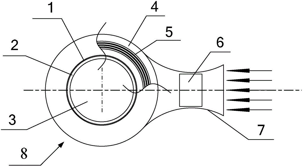
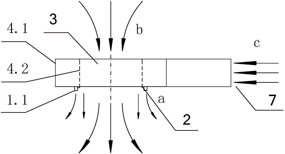
[0033] by Figure 1-3 As shown, the specific structure of the ceiling fan of the present invention is introduced:

[0034] The ceiling-mounted fan adopts a bladeless fan assembly as an air supply mechanism. Preferably, the ceiling-mounted fan is installed indoors and used as an indoor unit. Under normal circumstances, the blower fan has a housing and a panel facing the indoor space, the bladeless fan assembly is installed in the housing, and the air from the air outlet is sent into the room through the pan...


PUM


Abstract

The invention aims to provide a ceiling fan for solving the problem of inlet and outlet air heat short circuit in traditional ceiling fans. The ceiling fan comprises a bladeless fan component serving as an air blowing mechanism of the fan. The bladeless fan structure is applied to the ceiling fan; and the structural characteristics that air inlet and outlet directions of the bladeless fan are staggered in the space, the distance between the air inlet and the air outlet is far, and the mutual interference of inlet and outlet air flows is small are fully utilized, so that the problem of inlet and outlet air heat short circuit in the traditional ceiling fans is effectively prevented.

Description

technical field [0001] The invention relates to the field of air conditioning, in particular to a ceiling fan, in particular to an indoor unit of the ceiling fan. Background technique [0002] The ceiling fan (also known as patio fan) of the current central air-conditioning terminal device, as disclosed in Chinese patent document CN104564743A, has a quadrilateral structure, and the panel of the patio fan has an air inlet panel and a frame, and the frame is arranged on the ceiling. There are air outlets and air return outlets on the frame, the return air outlet is set in the center of the panel, the number of air outlets is generally 4, and they are respectively arranged on the four sides of the frame, and the air is sent from the ceiling to the room at a certain angle, that is, along the The four air outlets are respectively set at angles to supply air in four directions. [0003] The air supply mode of the existing patio machine blows out heat-exchange air. In this structu...

Claims


Application Information

Patent Timeline
Patent Type & Authority Applications(China)
IPC IPC(8): F24F1/00F24F13/06F24F13/30
CPCF24F1/0018F24F1/0059F24F13/06F24F13/30
Inventor 毛健罗苏瑜
Owner GREE ELECTRIC APPLIANCES INC
Why Eureka
Try Eureka