
An attached air duct system for building exterior walls

A technology for building exterior walls and air ducts, applied in ventilation systems, air conditioning systems, applications, etc., can solve problems such as difficult to improve, and achieve the effect of increasing the scope and effect, expanding the radiation scope, and outstanding circulation and purification effects.

Active Publication Date: 2017-12-26
HARBIN INST OF TECH
View PDF7 Cites 0 Cited by
  • Summary
  • Abstract
  • Description
  • Claims
  • Application Information

AI Technical Summary

Problems solved by technology

[0003] The purpose of the present invention is to provide an attached air duct system for building exterior walls, to solve the problem of street canyons caused by unfavorable weather conditions such as static wind and temperature inversion in heavily polluted street canyons with more automobile exhaust emissions. It is difficult to solve the problem of air pollution accumulation in the environment, and it is difficult to improve the local environmental microclimate

Method used


Image

  • An attached air duct system for building exterior walls
  • An attached air duct system for building exterior walls
  • An attached air duct system for building exterior walls

Examples


specific Embodiment approach 1

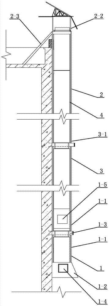
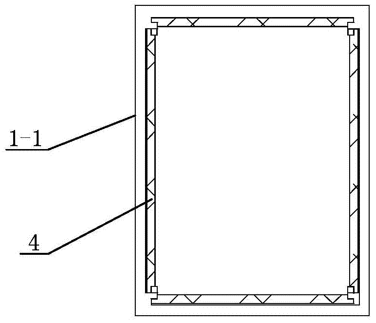
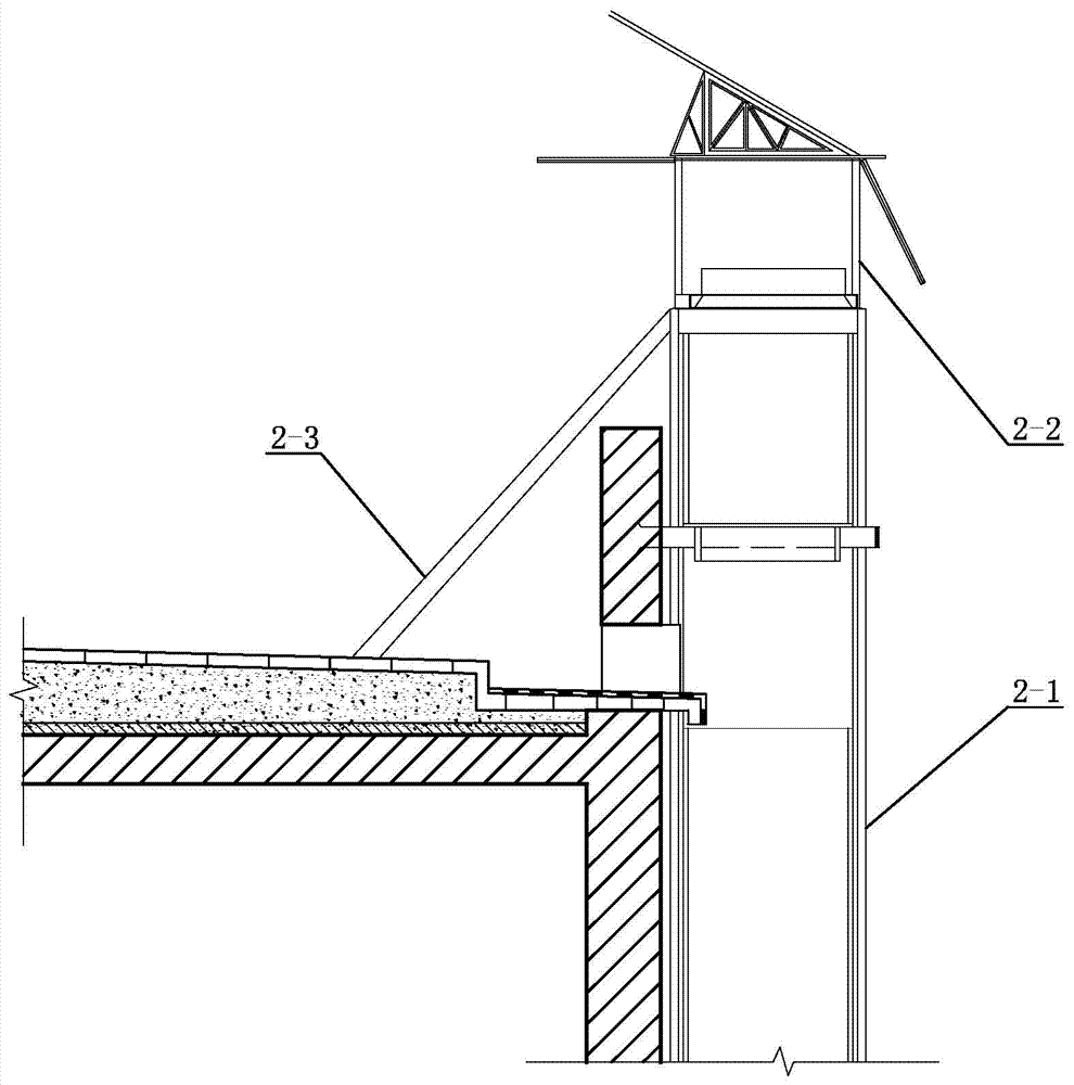
[0029] Specific implementation mode one: combine Figure 1 to Figure 12 Describe this embodiment, this embodiment comprises bottom air cylinder assembly 1, top air cylinder assembly 2, vegetation interlayer 4, a plurality of standard part air cylinder assemblies 3, described top air cylinder assembly 2, a plurality of standard part air cylinder assemblies 3 and the bottom air cylinder assembly 1 are located on the exterior wall of the building, and the top air cylinder assembly 2, a plurality of standard air cylinder assemblies 3 and the bottom air cylinder assembly 1 are sequentially connected from top to bottom to form an air duct;

[0030] The bottom air cylinder assembly 1 includes a bottom air cylinder body 1-1, an air intake hood 1-2 and a fixing clip 1-3, the bottom end of the bottom air cylinder body 1-1 is connected with an air intake hood 1-2, The bottom of the air inlet hood 1-2 is the main air inlet, the side wall of the air inlet hood 1-2 is processed with a side ...

specific Embodiment approach 2

[0037] Specific implementation mode two: combination figure 1 To illustrate this embodiment, in this embodiment, an auxiliary air inlet 1-5 is also processed on the side wall of the bottom air duct body 1-1, and an auxiliary air inlet 1-5 is formed between the auxiliary air inlet 1-5 and the top of the air inlet cover 1-2. The vertical distance is 3~5m.

[0038] In this embodiment, the vertical distance between the lateral air inlet 1-4 and the bottom of the wind inlet hood 1-2 is 10-20 cm; There are auxiliary air inlets 1-5. In this embodiment, the setting positions of the auxiliary air inlets 1-5 are flexibly set according to specific conditions, and they are used to absorb air pollution from floors in different bottom areas. Usually, under the effect of the vertical vortex of the street, the first to third floors on the ground are the most seriously polluted areas by street vehicle exhaust, and the second to third floors are usually the most polluted airspace, so auxiliar...

specific Embodiment approach 3

[0039] Specific implementation mode three: combination figure 1 , Figure 4 , Figure 5 and Figure 8 Describe this embodiment, in this embodiment, between every two adjacent standard part air cylinder bodies 3-1, there is a variable-diameter tenon joint or elastic connection; The lowermost standard fan cylinder body 3-1 is connected with variable diameter tenon or elastic connection; the top fan cylinder body 2-1 is connected with the uppermost standard fan cylinder body 3-1 among multiple standard fan cylinder assemblies 3 1 between variable diameter mortise joint or elastic connection. In this embodiment, the elastic connection needs to be realized by means of the elastic connector 18. The elastic connector 18 is a sleeve made of elastic material. 18 is fixedly connected between every two adjacent standard part air duct bodies 3-1 to realize the elastic connection of the two, which enhances the flexibility of the present invention, and is similar to the top of the botto...


PUM


Abstract

The invention relates to an air duct system, in particular to an attached type air duct system for a building external wall. In seriously polluted street canyons where automobile exhaust is released massively, the problem of air pollution concentration in the street canyons is difficult to solve due to adverse weather conditions such as calm wind and temperature inversion, and the microclimate of a local environment is difficult to improve. The attached type air duct system for the building external wall comprises a bottom air tunnel assembly, a top air tunnel assembly, a vegetation interlayer and a plurality of standard part air tunnel assemblies. The top air tunnel assembly, the standard part air tunnel assemblies and the bottom air tunnel assembly are sequentially communicated from top to bottom and are all located on the building external wall. The bottom end of a bottom air tunnel body is communicated with an air intake hood, the bottom of the air intake hook is a main air inlet, a lateral air inlet is formed in the sidewall of the air intake hood, and the bottom air tunnel body is fixedly connected to the building external wall through a fixing clamp. An air hood is arranged on the top of a top air tunnel body, and a diagonal brace is obliquely and fixedly connected between the top air tunnel body and a building top floor. The attached type air duct system for the building external wall is used for improving the quality of air between buildings.

Description

technical field [0001] The invention specifically relates to an attached air duct system for building exterior walls. Background technique [0002] With the rapid development of urban traffic, the number of motor vehicles in large and medium-sized cities is increasing year by year, and the pollution caused by motor vehicle exhaust emissions is also becoming more and more serious. Motor vehicle exhaust, including CO, NOx, hydrocarbons and particulate matter, is one of the main pollution sources that form PM2.5. Street canyons refer to the long and narrow valleys in the underlying surface of the urban atmospheric boundary layer formed by roads and surrounding continuous buildings in the city. The special geographical conditions and microclimate characteristics of urban street canyons will affect the transmission and diffusion of pollutants, which will adversely affect the health of people on the streets, including drivers and pedestrians. At the same time, natural ventilatio...

Claims


Application Information

Patent Timeline
Patent Type & Authority Patents(China)
IPC IPC(8): F24F7/04F24F13/28
CPCF24F7/04F24F13/28F24F8/10F24F8/175
Inventor 薛滨夏李同予梅梦月程一红李航
Owner HARBIN INST OF TECH
Learn More