Heating furnace structure

A heating furnace and heating element technology, used in electric furnace heating, lighting and heating equipment, furnaces, etc., can solve the problems of long cooling time and restrict productivity, save time, improve production efficiency, and quickly repair and replace the effect.

Active Publication Date: 2015-10-21
CHINA NUCLEAR POWER ENG CO LTD
View PDF3 Cites 7 Cited by
  • Summary
  • Abstract
  • Description
  • Claims
  • Application Information

AI Technical Summary

Problems solved by technology

When the material is toxic or radioactive, in order to avoid the spread of toxicity or radioactivity, it is necessary to heat the material in a closed environment and repair and replace the heating equipment, but the existing heating equipment cannot meet this requirement
In addition, for the batch heating method, since the furnace temperature needs to be lowered to a reasonable temperature before the materials can be taken out, the cooling time is very long, which greatly restricts the improvement of productivity

Method used


Image

  • Heating furnace structure
  • Heating furnace structure
  • Heating furnace structure

Examples


Embodiment Construction

[0020] The specific embodiments of the present invention will be described in further detail below in conjunction with the accompanying drawings.

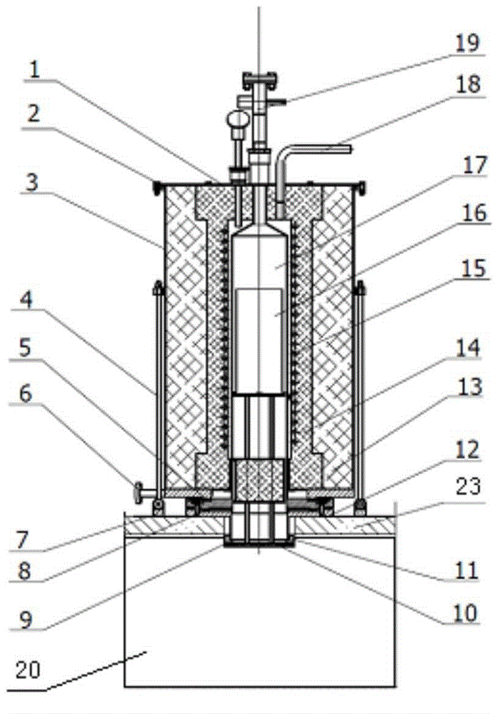
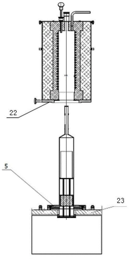
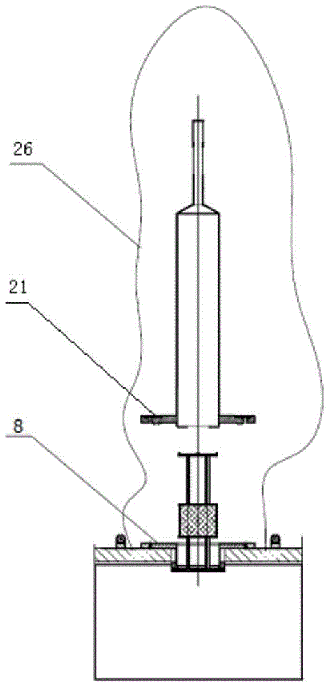
[0021] Such as Figure 1-4 As shown, the heating furnace structure provided by the present invention includes a furnace cover 1, a furnace cover sealing ring 2, a furnace shell 3, a locking mechanism 4, a furnace body gasket 5, a furnace inlet pipe 6, a locking fixing member 7, and a furnace Bilder sealing ring 8, furnace mouth sealing ring 9, furnace base 10, furnace mouth flange 11, furnace door flange 12, flexible insulation layer 13, rigid insulation layer 14, heating element 15, material container 16, furnace bladder 17, furnace row The air pipe 18, the furnace tube adapter 19, the chamber 20, the furnace flange 21, the furnace shell flange 22, the heating furnace installation platform 23, the insulation material 24, the bottom plate 25, and the bag seal 26.

[0022] Among them: the furnace cover 1 is a plate-shaped structure, and...


PUM


Abstract

The invention relates to a heating furnace structure. The heating furnace structure comprises a furnace body with an opening formed in the lower portion and a furnace pipe assembly penetrating through the furnace body from bottom to top. The furnace body is arranged on a heating installation platform of a box chamber. The furnace pipe assembly comprises a furnace pipe and a lifting furnace platform arranged in the furnace pipe. A furnace pipe flange is arranged on the periphery of the lower portion of the furnace pipe. The upper end of the furnace pipe flange is tightly matched with the bottom of the furnace body. The lower end of the furnace pipe flange is connected with a furnace door flange located on the box chamber. The bottom of the furnace platform is tightly matched with the furnace door flange. A furnace pipe sealing ring is arranged between the furnace pipe flange and the furnace door flange. A furnace mouth sealing ring is arranged between the furnace door flange and the furnace platform. By means of the heating furnace structure, materials can be heated in a closed environment, and an adverse effect of toxic or radioactive diffusion on the environment is avoided. Quick cooling can be achieved after heating, and work efficiency is improved; parts can be quickly overhauled and replaced, and time is saved.

Description

Technical field [0001] The invention belongs to the field of heating equipment, and specifically relates to a heating furnace structure. Background technique [0002] In the chemical industry, it is often necessary to heat materials. At present, most of the existing heating devices are non-sealed structures and only use ventilation means. When materials are toxic or radioactive, in order to avoid the spread of toxicity or radioactivity, the materials need to be heated in a closed environment, and the heating equipment must be overhauled and replaced, but the existing heating equipment cannot meet this requirement. In addition, for batch heating methods, the materials need to be lowered to a reasonable temperature before the materials can be taken out, and the cooling time is very long, which greatly restricts the increase in productivity. Summary of the invention [0003] Aiming at the defects in the prior art, the present invention provides a heating furnace structure, which ca...

Claims


Application Information

Patent Timeline
Patent Type & Authority Applications(China)
IPC IPC(8): F27B17/00F27D9/00F27D11/00
Inventor 降宇波梁汝囡吴德慧段宏王广开
Owner CHINA NUCLEAR POWER ENG CO LTD
Why Eureka
Try Eureka