
Method for detecting locomotive bearing fault

A technology for bearings and locomotives, applied in the field of locomotive bearing fault detection, can solve the problems of no early warning of locomotive bearing faults, bearings affecting the safe operation of locomotives, bearing failures, etc., to achieve the effect of avoiding unsafe accidents

Inactive Publication Date: 2015-10-21
杨玉娇 +2
View PDF6 Cites 34 Cited by
  • Summary
  • Abstract
  • Description
  • Claims
  • Application Information

AI Technical Summary

Problems solved by technology

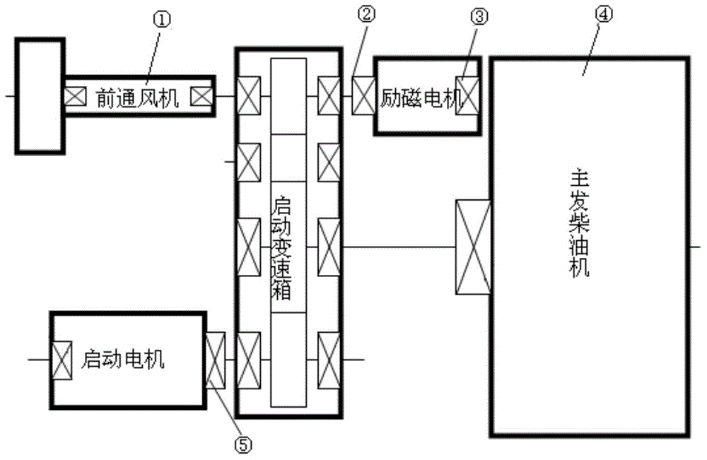
figure 1 The five components shown in are all connected by mechanical transmission relationship. If the bearing at one of the positions is damaged, it will directly affect the power source of the locomotive and make the main engine diesel unit unable to work normally. Failure will also affect the safe operation of the locomotive
[0005] It is precisely because the shafts (or rotors) carried by the bearings of the DF4B locomotives running on this line are in a full-rotation state for a long time, so it is particularly prone to overheating, coupled with the complex loads borne by the bearings Therefore, serious bearing failures such as broken cages and broken rolling elements are likely to occur when the locomotive is running, especially the bearings of the running part of the locomotive. Once a serious failure occurs during the operation of the locomotive, it will directly cause If the machine is broken, serious traffic accidents will occur
If early bearing failures can be detected timely and accurately and repaired, the occurrence of unsafe accidents will be greatly reduced. However, in the prior art, there is no method for early warning of locomotive bearing failures

Method used


Image

  • Method for detecting locomotive bearing fault
  • Method for detecting locomotive bearing fault
  • Method for detecting locomotive bearing fault

Examples


Embodiment Construction

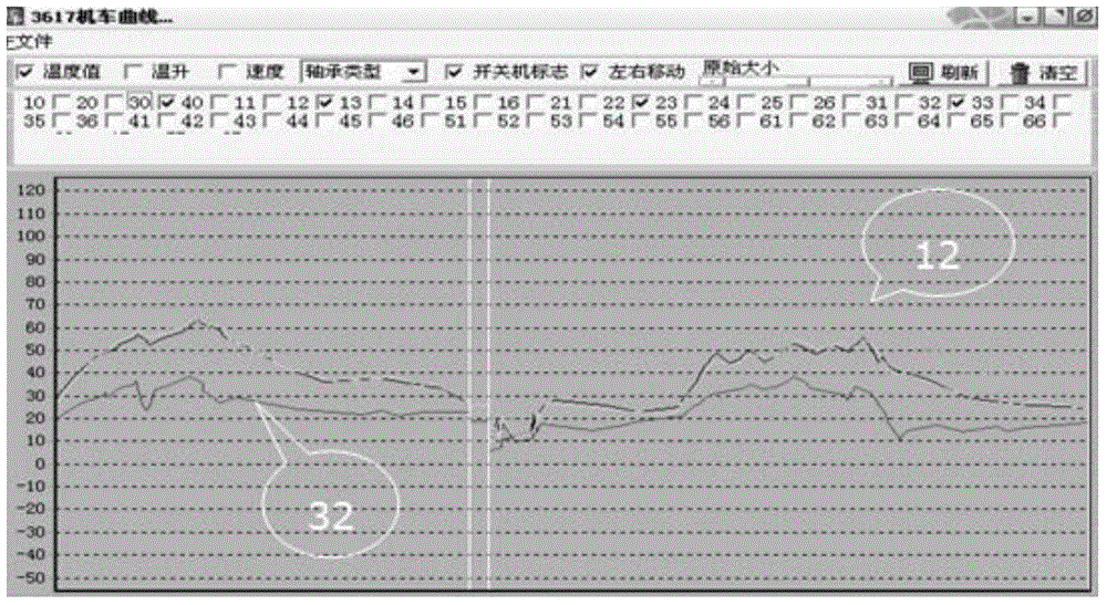
[0065] The invention provides a method for detecting faults of locomotive bearings, which uses a combination of real-time temperature monitoring, vibration monitoring and regular detection to prevent and control the faults of the bearings on the locomotive, thereby ensuring the safe operation of the locomotive.

[0066] Specifically, the method of the present invention includes a method for real-time temperature monitoring of important bearings on the locomotive, and the method for temperature monitoring includes the following steps:

[0067] Using multiple temperature sensors installed at multiple bearing housings of the locomotive to detect the temperature of multiple bearings to obtain the temperature signal of each bearing during the running of the locomotive;

[0068] By processing the real-time temperature signal of each bearing, a series of current bearing temperature values ​​of each bearing are obtained;

[0069] Connect a series of current bearing temperature values ...


PUM


Abstract

The invention discloses a method for detecting a locomotive bearing fault. For a practical condition of the locomotive, the method disclosed by the invention adopts a combination of a temperature detection method and a vibration detection method to perform detection on a bearing fault of the locomotive. When the temperature detection is employed to detect the locomotive bearing fault, a temperature trend analysis method and an advanced interference processing method of catching an early warning and protecting alarm. When the vibration method is adopted to detect the locomotive bearing fault, the combination of the simple diagnosis and the precise diagnosis and the combination of the vibration detection and shock pulse detection are adopted. As a result, the invention can perform early alarm on the axle fault of the locomotive, can promptly process the axles having an early stage fault, and prevent the unsafe accident from happening.

Description

technical field [0001] The invention relates to the technical field of locomotives, in particular to a method for detecting faults of locomotive bearings. Background technique [0002] For locomotives, especially locomotives operating in the Tianshan Mountains in southern Xinjiang and the edge of the Taklimakan Desert, the operating environment of the locomotives is extremely harsh due to their long running lines, many large ramps, strong wind and sand, and individual stations with an altitude of up to 3,000 meters. Therefore, the requirements for the safety and reliability of the locomotive, especially the bearings on the locomotive, are higher. [0003] Among them, the important bearings on the locomotive include: the bearings of the main diesel engine, the transmission shaft bearings of the starting gearbox, the bearings of the excitation motor, the bearings of the starting motor, the bearings of the front fan, the axle box bearings of the running part, and the traction m...

Claims


Application Information

Patent Timeline
Patent Type & Authority Applications(China)
IPC IPC(8): G01M13/04G01M17/08
Inventor 杨玉娇张征赵晓飞
Owner 杨玉娇
Learn More