
Intelligent LED discriminator

An intelligent and chip technology, applied in the field of discriminators, can solve problems such as defective products, visual fatigue, misjudgment, etc., to reduce the error rate, ensure efficiency and effect, and avoid eye fatigue.

Inactive Publication Date: 2015-10-21
NANJING INST OF RAILWAY TECH
View PDF6 Cites 0 Cited by
  • Summary
  • Abstract
  • Description
  • Claims
  • Application Information

AI Technical Summary

Problems solved by technology

In the manufacturing process, checking whether the LED is installed correctly can usually only be identified by the eyes of the worker, and long hours of work often cause visual fatigue and misjudgment, resulting in defective products

Method used


Image

  • Intelligent LED discriminator
  • Intelligent LED discriminator
  • Intelligent LED discriminator

Examples


Embodiment Construction

[0016] The present invention will be further described in detail below in conjunction with the accompanying drawings and examples. The following examples are explanations of the present invention and the present invention is not limited to the following examples.

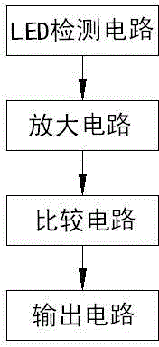
[0017] As shown in the figure, an intelligent LED discriminator of the present invention includes two LED detection circuits, an amplification circuit, a comparison circuit and an output circuit, the two LED detection circuits are connected to the amplification circuit, and the amplification circuit is connected to the comparison circuit. The comparison circuit is connected to the output circuit.

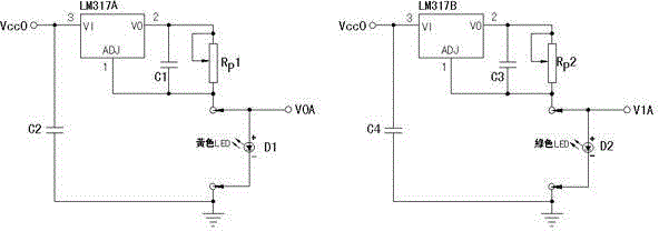
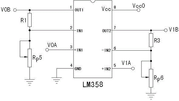
[0018] LED detection circuit includes LM317A chip, LM317B chip, four filter capacitors C1, C2, C3, C4, two adjustable resistors RP1, RP2 and two LED lights D1, D2 to be tested, 3 pins of LM317A chip and power supply VCC0 and One end of the filter capacitor C2 is connected, the other end of the filter capacitor C2 is groun...


PUM


Abstract

The invention discloses an intelligent LED discriminator, including two LED detection circuits, an amplification circuit, a comparison circuit and an output circuit. The two LED detection circuits are connected with the amplification circuit, the amplification circuit is connected with the comparison circuit, and the comparison circuit is connected with the output circuit. According to the intelligent LED discriminator provided by the invention, detected forward bias voltage of an LED lamp is amplified, and is then compared with preset voltage, and a result is output, thereby driving a relay, and controlling on-off of an indicator light, the operation is simple, and the LED lamp does not need to be stared for a long time, thereby avoiding eyestrain, and reducing a detection result error rate caused by detection fatigue.

Description

technical field [0001] The invention relates to a discriminator, in particular to an intelligent LED discriminator. Background technique [0002] Light-emitting diode LED is a solid-state semiconductor device that can directly convert electricity into light. In daily life, we often use LEDs to emit different colors of light to indicate that instruments and electronic devices are in different working states. For example: the computer network interface connector usually has an RJ-45 interface on the end face, and there are 2 LEDs, which can emit green light and yellow light respectively. When the network card is working, the working condition of the network card can be judged by the color and flashing state of the LED. In the manufacturing process, checking whether the LED is installed correctly can usually only be identified by the eyes of the worker, and long hours of work often cause visual fatigue and misjudgment, resulting in defective products. In order to facilitate ...

Claims


Application Information

Patent Timeline
IPC IPC(8): G01R31/27
Inventor 王啸东王茜薇
Owner NANJING INST OF RAILWAY TECH
Learn More