Supercharge Your Innovation With Domain-Expert AI Agents!

Peak current control circuit

A peak current control and circuit technology, applied in control/regulation systems, regulation of electrical variables, instruments, etc., can solve problems such as variable frequency work that cannot realize dynamic changes in input voltage or load, to improve dynamic response, reduce power consumption, The effect of improving system response

Active Publication Date: 2015-10-21
NANJING SILERGY SEMICON TECH CO LTD
View PDF8 Cites 14 Cited by
  • Summary
  • Abstract
  • Description
  • Claims
  • Application Information

AI Technical Summary

Problems solved by technology

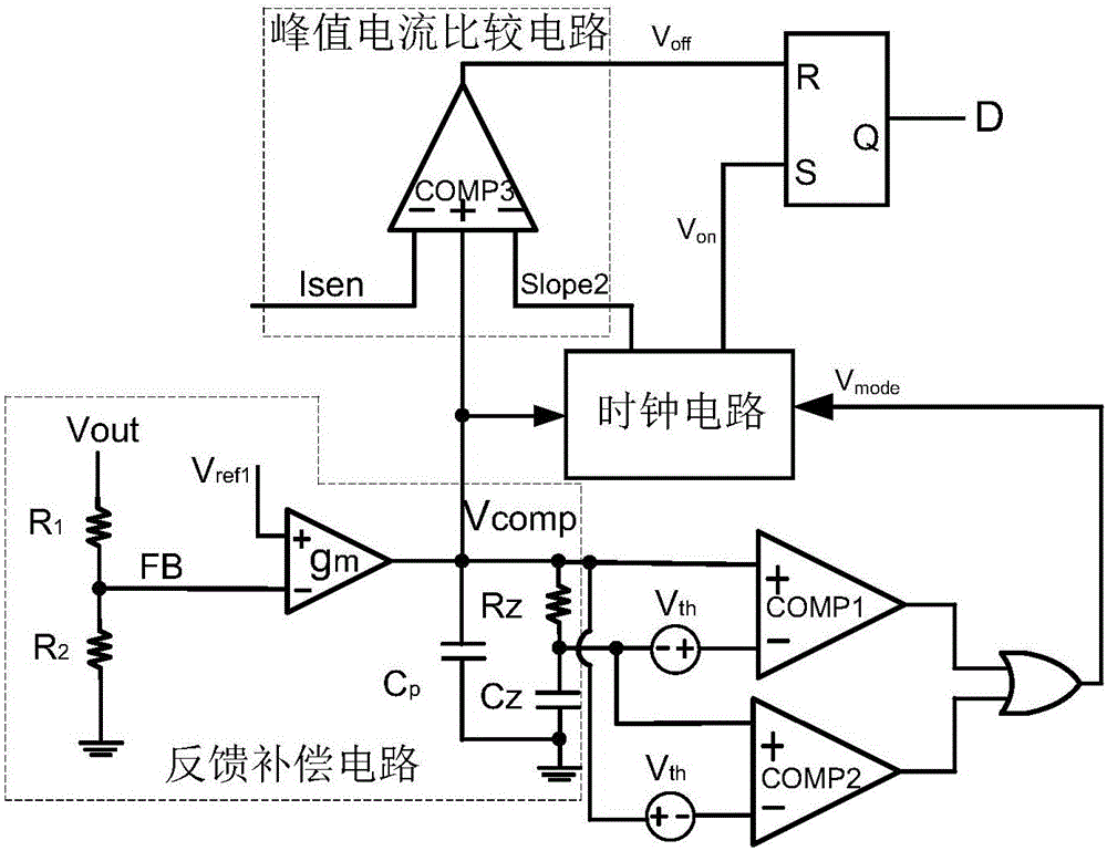
[0004] In view of this, the purpose of the present invention is to provide a peak current control circuit to solve the technical problem in the prior art that the variable frequency operation of input voltage or load dynamic change cannot be realized

Method used


Image

  • Peak current control circuit
  • Peak current control circuit
  • Peak current control circuit

Examples


Embodiment Construction

[0022] Preferred embodiments of the present invention will be described in detail below with reference to the accompanying drawings, but the present invention is not limited to these embodiments. The present invention covers any alternatives, modifications, equivalent methods and schemes made within the spirit and scope of the present invention.

[0023] In order to provide the public with a thorough understanding of the present invention, specific details are set forth in the following preferred embodiments of the present invention, but those skilled in the art can fully understand the present invention without the description of these details.

[0024] In the following paragraphs the invention is described more specifically by way of example with reference to the accompanying drawings. It should be noted that all the drawings are in simplified form and use inaccurate scales, which are only used to facilitate and clearly assist the purpose of illustrating the embodiments of t...


PUM


Abstract

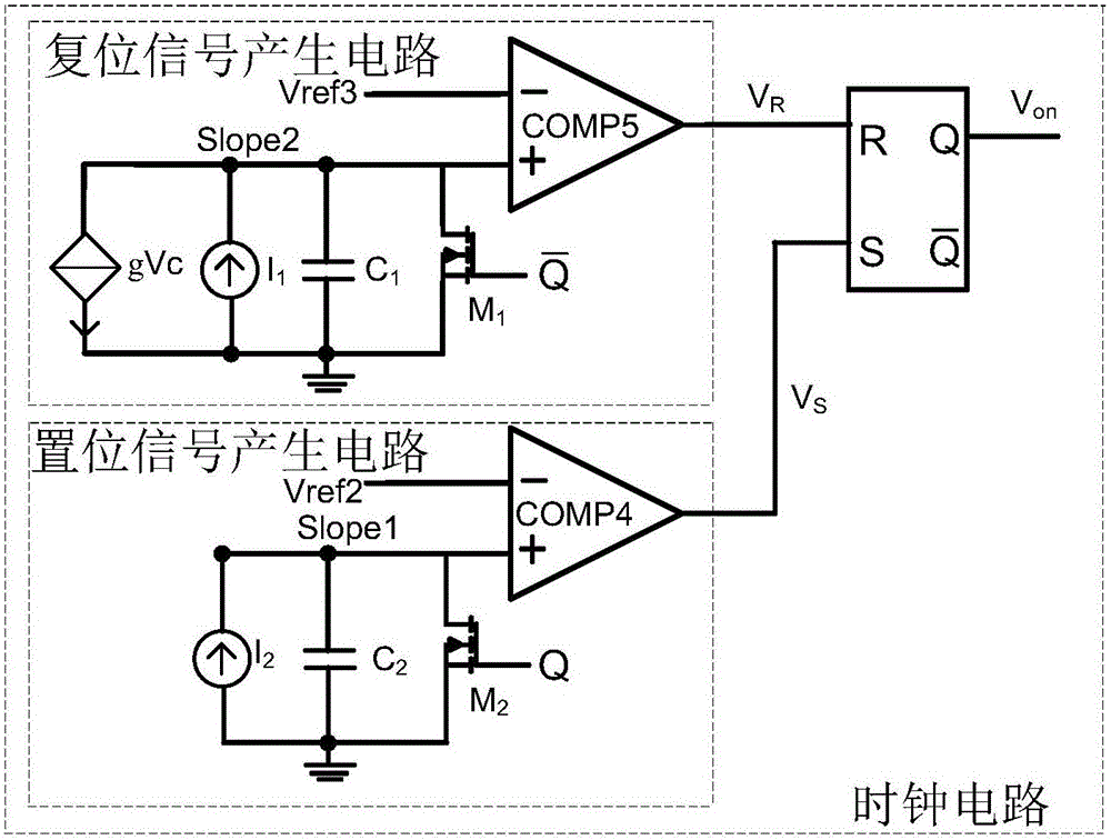
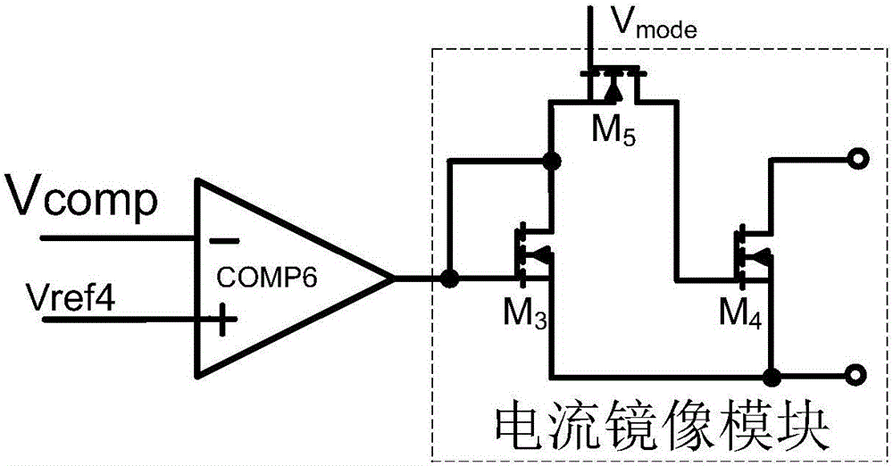
The invention discloses a peak current control circuit based on a peak current control mode to determine whether input voltage or load dynamically changes via detecting charge-discharging conditions of a compensation module. When input voltage or load dynamically changes, the peak current control circuit first maintains voltage-controlled current source constant and then adjusts the voltage-controlled current source to achieve frequency conversion work after a steady state is realized; system response is improved; and when a steady state is achieved again, the voltage-controlled current source is constant. Switching frequency can be adaptively adjusted according to the dynamic changes of the input voltage or load, so dynamic response can be improved and power consumption can be reduced.

Description

technical field [0001] The invention relates to the technical field of power electronics, in particular to a peak current control circuit. Background technique [0002] In applications such as voltage regulators and LED drive circuits, a corresponding control circuit is required to control the on-off of the power switch tube to obtain a corresponding output. The fixed-frequency peak current control circuit in the prior art obtains a feedback compensation signal by sampling the output voltage and performing error processing with the corresponding reference voltage, and compares the feedback compensation signal with the inductor current value to obtain the comparison result and compare it with the clock The signals are used together to generate a duty cycle signal for controlling the main power switch. [0003] Since the above prior art is based on constant frequency control, it is well known that if the original constant frequency operation is maintained when the input volta...

Claims


Application Information

Patent Timeline
Patent Type & Authority Applications(China)
IPC IPC(8): G05F1/10
Inventor 毛浪
Owner NANJING SILERGY SEMICON TECH CO LTD
Features
  • R&D
  • Intellectual Property
  • Life Sciences
  • Materials
  • Tech Scout
  • Unparalleled Data Quality
  • Higher Quality Content
  • 60% Fewer Hallucinations
Learn More