Scanning driving circuit

A technology for scanning driving circuits and scanning lines, which can be applied to instruments, static indicators, etc., and can solve the problems of low reliability of scanning driving circuits.

Active Publication Date: 2015-10-21
TCL CHINA STAR OPTOELECTRONICS TECH CO LTD
View PDF5 Cites 19 Cited by
  • Summary
  • Abstract
  • Description
  • Claims
  • Application Information

AI Technical Summary

Problems solved by technology

[0005] The purpose of the present invention is to provide a scanning driving circuit with high rel

Method used


Image

  • Scanning driving circuit
  • Scanning driving circuit
  • Scanning driving circuit

Examples


Embodiment Construction

[0093] The following descriptions of the various embodiments refer to the accompanying drawings to illustrate specific embodiments in which the present invention can be practiced. The directional terms mentioned in the present invention, such as "up", "down", "front", "back", "left", "right", "inside", "outside", "side", etc., are for reference only The orientation of the attached schema. Therefore, the directional terms used are used to illustrate and understand the present invention, but not to limit the present invention.

[0094] In the figures, structurally similar units are denoted by the same reference numerals.

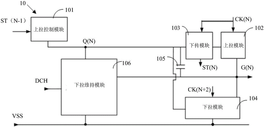
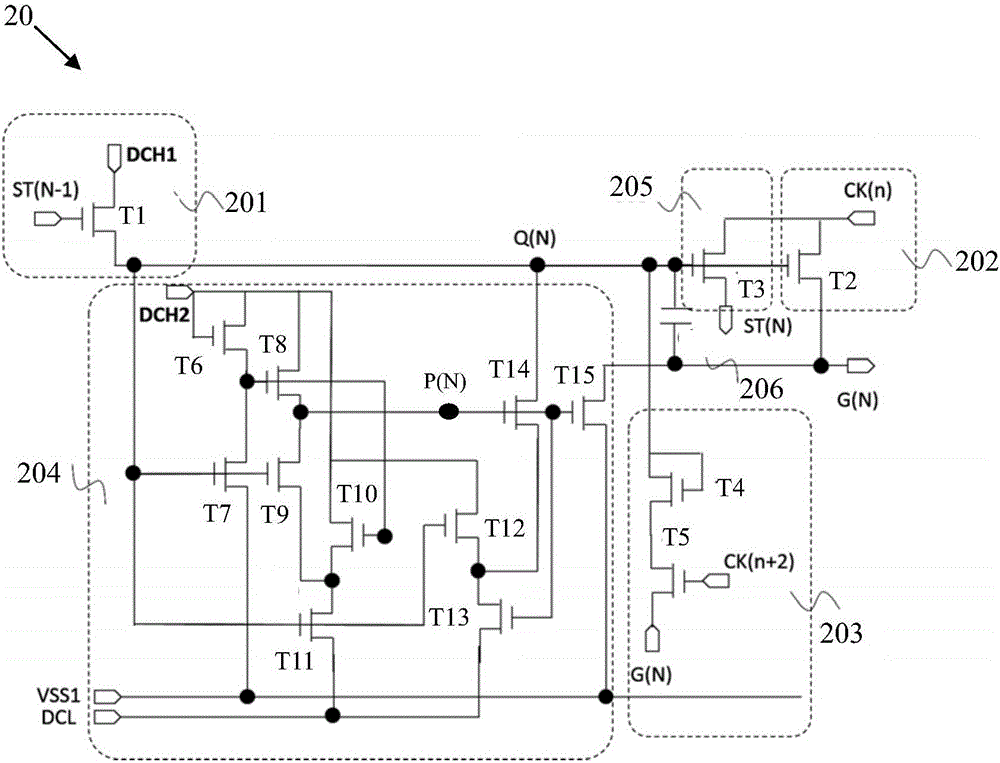
[0095] Please refer to figure 2 , figure 2 It is a structural schematic diagram of the first preferred embodiment of the scanning driving circuit of the present invention. The scan driving circuit 20 of this preferred embodiment includes a pull-up control module 201 , a pull-up module 202 , a pull-down module 203 , a pull-down maintenance module 204 , a ...


PUM


Abstract

The invention provides a scanning driving circuit. The scanning driving circuit is used for performing driving operation on cascaded scanning lines. The scanning driving circuit includes a pull-up control module, a pull-up module, a pull-down module, a pull-down maintaining module, a downloading module and a bootstrap capacitor. According to the scanning driving circuit of the invention, first constant voltage high electric level and second constant-voltage high electric level are set, so that the ability of control on q-point potential can be strengthened, and the reliability of the scanning driving circuit can be improved.

Description

technical field [0001] The invention relates to the field of display driving, in particular to a scanning driving circuit. Background technique [0002] Gate Driver On Array, referred to as GOA, is to make a scan drive circuit on the array substrate of the existing thin film transistor liquid crystal display to realize the drive mode of progressive scan of the scan lines. The schematic diagram of the structure of the existing scan driving circuit is as follows: figure 1 As shown, the scan driving circuit 10 includes a pull-up control module 101 , a pull-up module 102 , a downlink module 103 , a pull-down module 104 , a bootstrap capacitor 105 and a pull-down maintenance module 106 . [0003] In the scan driving circuit, when the threshold voltages of the elements do not match, circuit failure may occur. This is due to the fact that the pull-down maintenance circuit module’s ability to control the potential of the Q point is weakened when the threshold power supply of the c...

Claims


Application Information

Patent Timeline
IPC IPC(8): G09G3/36
CPCG09G3/36
Inventor 戴超
Owner TCL CHINA STAR OPTOELECTRONICS TECH CO LTD
Why Eureka
Try Eureka